Chemical Adsorption Refrigeration System Driven by Engine Exhaust Gas

A chemical adsorption and refrigeration system technology, which is applied to the operation mode of the machine, refrigerator, refrigeration and liquefaction, etc., can solve the problems of air leakage and water leakage, deformation and cracking of the inner wall of the generator, and blockage of the flue pipe, so as to avoid spraying The effects of hole blockage, increased refrigeration depth, and improved cooling efficiency

Active Publication Date: 2016-05-25
武汉箕星制冷有限公司
View PDF7 Cites 0 Cited by
  • Summary
  • Abstract
  • Description
  • Claims
  • Application Information

AI Technical Summary

Problems solved by technology

[0002] In the technology and product research of thermal adsorption refrigeration using the heat source of high-temperature engine exhaust gas, mechanical smoke plate valve structure was often used in the past to control and switch the channel of engine exhaust gas and cooling water. This mechanism has the following defects: due to the exhaust temperature As high as 300-600°C, it is difficult for the mechanical smoke plate valve to find a sealing material under this temperature condition, so there are inevitably air and water leakage problems; the machining process of the mechanical smoke plate valve is complicated, the cycle is long, and the cost is high ;Under high temperature conditions, mechanical smoke plate valves are prone to thermal expansion and contraction deformation, jamming and other mechanical failures, which affect the normal operation of the system; corrosion problem
However, in actual application, since most of the engine exhaust heat is heated to the buoy and the inner wall of the generator near the buoy, the buoy and the inner wall of the generator are seriously deformed and cracked, and the flue pipe is blocked, which seriously wastes the energy required by the adsorption bed. engine exhaust heat

Method used


Image

  • Chemical Adsorption Refrigeration System Driven by Engine Exhaust Gas
  • Chemical Adsorption Refrigeration System Driven by Engine Exhaust Gas
  • Chemical Adsorption Refrigeration System Driven by Engine Exhaust Gas

Examples


Embodiment 1

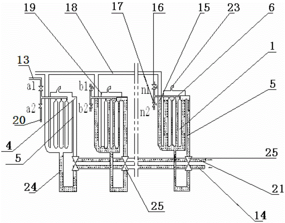
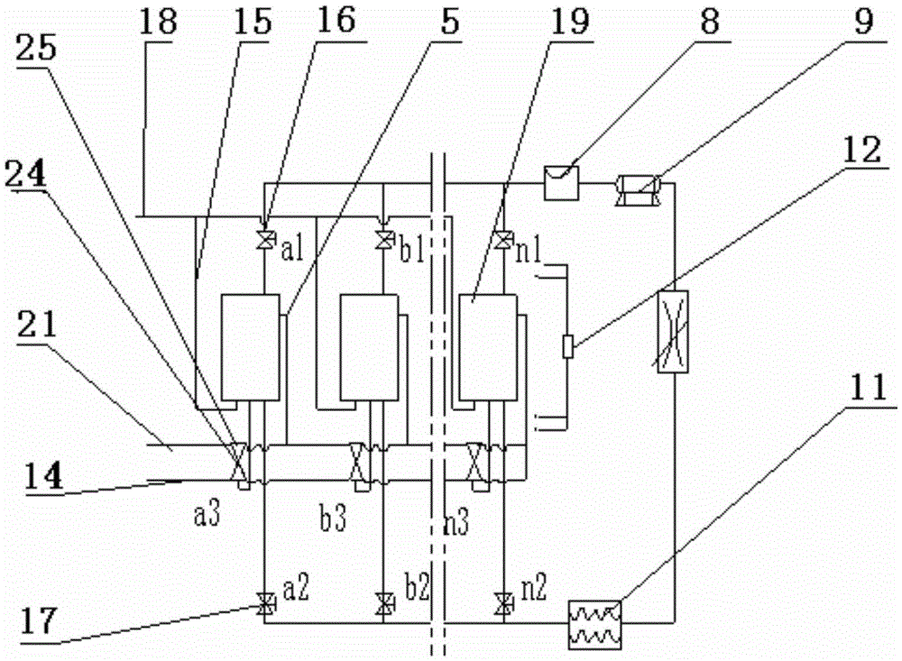
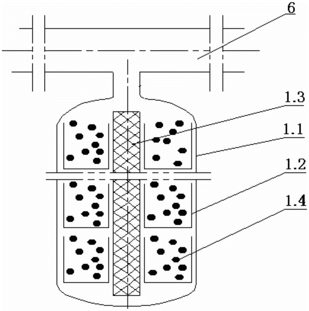
[0034] Such as figure 1 As shown, it is suitable for the prototype of the chemical adsorption refrigeration system driven by engine exhaust gas. Its adsorption bed is composed of three sets of adsorption bed assemblies 1, and each set of adsorption bed assemblies 1 includes four adsorption bed unit tubes 3 of φ70*2*500. , commonly connected to the gas main pipe 6 used for the inlet and outlet of the adsorption bed, the outside of the gas main pipe 6 is respectively connected to the one-way control valve group 16 of the deamination passage and the one-way control valve group 17 of the ammonia absorption passage; the flue gas inlet pipe 15 connects with the adsorption bed from the bottom The inner cavity is connected, the cooling water overflow pipe 5 of the adsorption bed is connected with the inner cavity of the adsorption bed from the upper side, and the U-shaped water seal pipe 24 is connected with the inner cavity of the adsorption bed from the bottom. The water level diffe...


PUM


Abstract

The invention discloses a chemical adsorption refrigeration system driven by taking engine tail gas as energy. The chemical adsorption refrigeration system comprises N adsorption bed assemblies; each adsorption bed assembly comprises an adsorption bed unit pipe assembly, an ammonia adsorption pipeline, an ammonia desorption pipeline, a smoke inlet pipeline, a cooling water inlet pipeline and a cooling water outlet pipeline; each adsorption bed unit pipe assembly comprises M adsorption unit pipes; each adsorption unit pipe comprises an adsorption outer pipe, multiple trays arranged in the adsorption outer pipe and filter nets arranged in the middles of the trays; an adsorbent is arranged in each tray; the top ends of the adsorption outer pipes are connected with an air total pipe; a condenser, a liquid ammonia storage tank, a throttler and an evaporator are connected between the ammonia desorption pipeline and the ammonia adsorption pipeline in sequence. The chemical adsorption refrigeration system is simple in structure, high in reliability and good in cooling effect.

Description

technical field [0001] The invention relates to a chemical adsorption thermal refrigeration system, in particular to a chemical adsorption refrigeration system driven by engine exhaust gas. Background technique [0002] In the technology and product research of thermal adsorption refrigeration using the heat source of high-temperature engine exhaust gas, mechanical smoke plate valve structure was often used in the past to control and switch the channel of engine exhaust gas and cooling water. This mechanism has the following defects: due to the exhaust temperature As high as 300-600°C, it is difficult for the mechanical smoke plate valve to find a sealing material under this temperature condition, so there are inevitably air and water leakage problems; the machining process of the mechanical smoke plate valve is complicated, the cycle is long, and the cost is high ;Under high temperature conditions, mechanical smoke plate valves are prone to thermal expansion and contraction...

Claims


Application Information

Patent Timeline
Patent Type & Authority Patents(China)
IPC IPC(8): F25B17/08F25B27/02
CPCY02A30/274Y02B30/625
Inventor 张阳
Owner 武汉箕星制冷有限公司
Why Eureka
Try Eureka