Rare-earth permanent magnet and preparation method thereof

A technology of rare earth permanent magnets and permanent magnets, which is applied in the direction of magnetic objects, permanent magnets, inductors/transformers/magnets, etc., and can solve the problems of magnet corrosion resistance decline

Active Publication Date: 2014-09-17
BEIJING ZHONG KE SAN HUAN HI TECH +1
View PDF7 Cites 26 Cited by
  • Summary
  • Abstract
  • Description
  • Claims
  • Application Information

AI Technical Summary

Problems solved by technology

However, excessive rare earth can easily lead to a decrease in the corrosion resistance of the magnet

Method used


Image

  • Rare-earth permanent magnet and preparation method thereof
  • Rare-earth permanent magnet and preparation method thereof

Examples


Embodiment 1

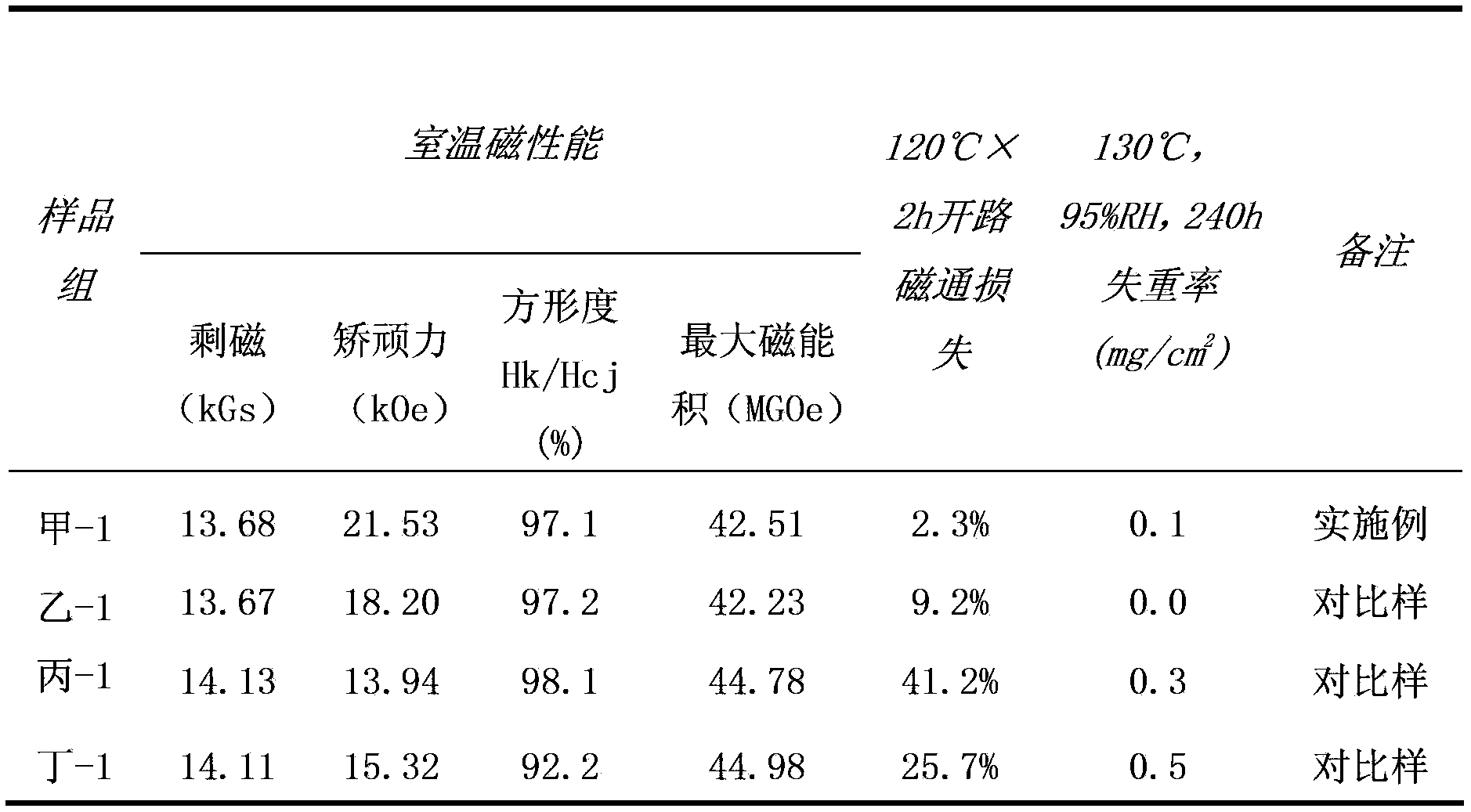
[0046] Smelt the alloy to get (Nd,Pr) 10 (Fe,Co) 81 B 7 (Nb,V) 2 The main phase alloy strips and (Nd, Dy) 40 Fe 30 (Cu,Al) 30 Auxiliary alloy ingot blocks, the flakes are subjected to mechanical coarse crushing, hydrogen crushing, and jet milling, and the ingot blocks are subjected to mechanical coarse crushing, hydrogen crushing, and ball milling to obtain a main phase alloy powder with a D50 of 7.5 μm and a D90 / D10 The D50 of the auxiliary alloy powder is 2 μm; then the above two powders are fully mixed at a mass percentage of 85:15, and then subjected to 2.0T orientation magnetic field orientation pressing, 180MPa isostatic pressing, and the green body is sintered at 1050°C for 2.5h. To obtain a rough magnet, the surface of the sintered rough magnet was ground to remove scale, and the surface was cleaned with lye. The obtained Φ10.1mm×10.1mm magnet samples were divided into two groups, A-1 and B-1.

[0047] The samples in group B-1 are comparative samples without any ...

Embodiment 2

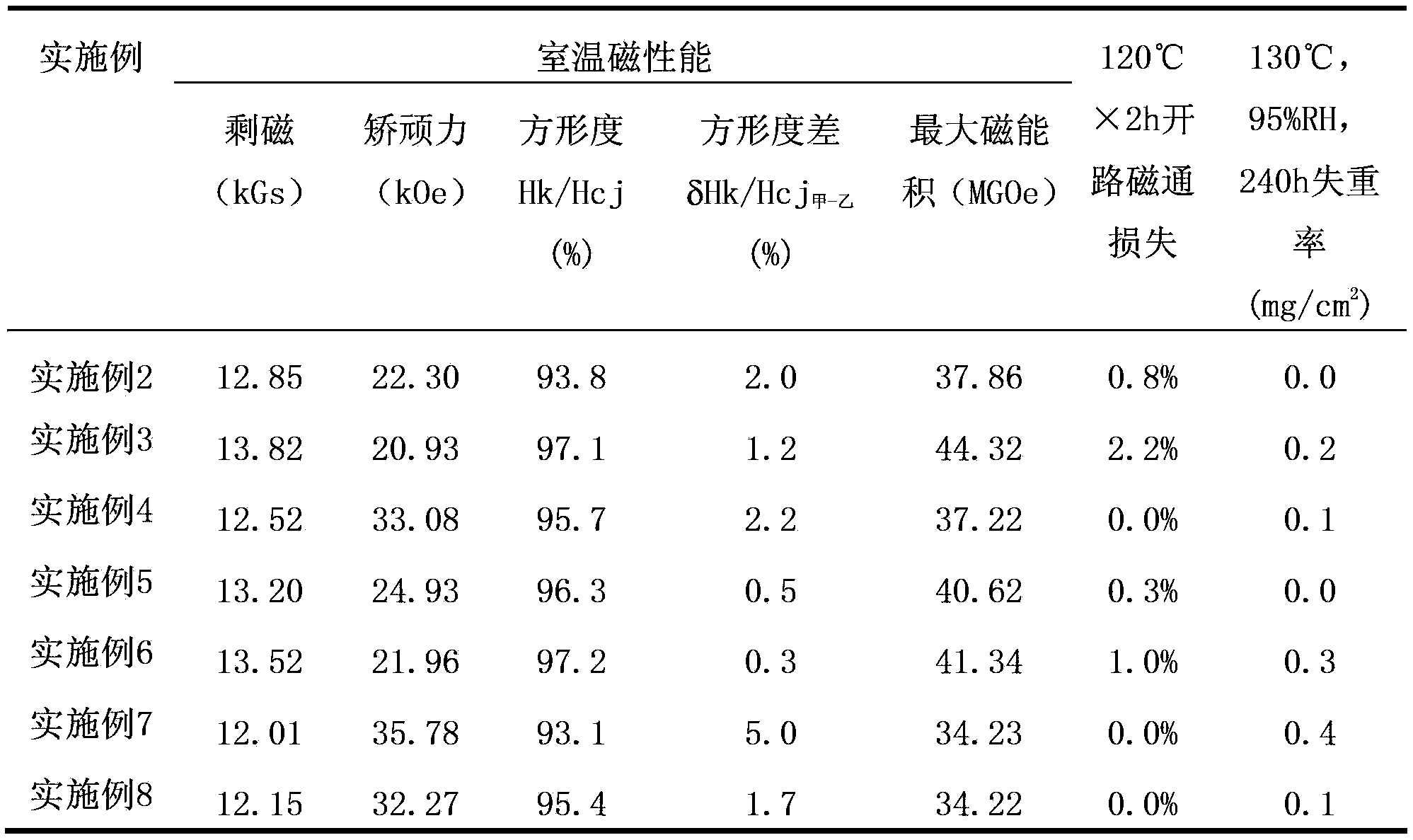
[0060] Smelt the alloy to get (Nd,Pr) 8 (Fe,Co) 81.1 B 7.4 (Nb, Zr) 3.5 The main phase alloy flakes and Nd 60 (Fe,Co) 25.5 B 5.1 (Cu,Ga) 9.4 Auxiliary alloy ingot blocks, the flakes are subjected to mechanical coarse crushing, hydrogen crushing, and jet milling, and the ingot blocks are subjected to mechanical coarse crushing, hydrogen crushing, and ball milling to obtain a main phase alloy powder with a D50 of 3.0 μm and a D90 / D10 15.0, D50 of the auxiliary alloy powder is 0.3 μm; then the above two powders are fully mixed with a mass percentage of 70:30, and then subjected to 2.0T orientation magnetic field orientation pressing, 180MPa isostatic pressing, and the green body is sintered at 1100°C for 0.2h , to obtain a rough magnet, grind the surface of the sintered rough magnet, wash the surface with lye, and obtain a Φ20mm×5mm rough magnet.

[0061] The obtained rough magnet sample surface layout DyF 3 , Dy 2 o 3 and DyOF three powders, their mass percentages are ...

Embodiment 3

[0068] Smelt the alloy to get (Nd,Pr) 15.2 (Fe,Co) 75.8 B 5.8 (Nb,Zr,V) 3.2 The main phase alloy flakes and Nd 60 (Al,Zn) 40 Auxiliary alloy ingot blocks, the flakes are subjected to mechanical coarse crushing, hydrogen crushing, and jet milling, and the ingot blocks are subjected to mechanical coarse crushing, hydrogen crushing, and ball milling to obtain a main phase alloy powder with a D50 of 10.0 μm and a D90 / D10 The D50 of the auxiliary alloy powder is 8.0 μm; then the above two powders are fully mixed at a mass percentage of 99:1, and then subjected to 2.0T orientation magnetic field orientation pressing, 180MPa isostatic pressing, and the green body is sintered at 1060°C for 3h. A rough magnet is obtained, the surface of the sintered rough magnet is ground, and the surface is cleaned with lye to obtain a Φ15mm×15mm rough magnet.

[0069] The obtained rough magnet sample surface layout DyF 3 Powder, the average particle size is 40μm, the solution is prepared accord...


PUM

PropertyMeasurementUnit
particle sizeaaaaaaaaaa
thicknessaaaaaaaaaa
thicknessaaaaaaaaaa

Abstract

The invention discloses a rare-earth permanent magnet. The rare-earth permanent magnet mainly comprises the following components in percentage by atom: 12.1-16.2 percent of R, 0-3.4 percent of M1, 0-7.2 percent of M2, 5.1-7.4 percent of B and the balance of T, wherein the R is at least one of rear-earth elements including Y and Sc, and at least contains Nd; the M1 is at least one of Nb, Ti, Zr, V, Cr, Mo and Mn; the M2 is at least one of Al, Cu, Zn, Ga, In, Ge and Sn; the T is Fe or Fe and Co. A preparation method of the rare-earth permanent magnet comprises the processes of preparation of a magnet blank, coating, thermal treatment, and ageing, wherein the magnet blank is prepared by using a double-alloy method or a composite powder method. According to the magnet prepared by using the method, the coercive force, the temperature resistance and the corrosion resistance of a larger-size magnet can be improved, and the residual magnetism and the squareness of the magnet are not reduced.

Description

technical field [0001] The invention relates to a rare earth permanent magnet and a preparation method thereof, in particular to an NdFeB permanent magnet and a preparation method thereof. Background technique [0002] With its excellent magnetic properties, sintered NdFeB magnets are continuously reduced in volume and weight, so they adapt to the current trend of energy saving and environmental protection. In recent years, they have been widely used in air-conditioning motors, hybrid vehicles and wind power generation. The use of magnets in these fields requires high magnetic properties in many cases, including high remanence, coercive force, and squareness of the demagnetization curve (the squareness of the magnet refers to the magnetic polarization on the J-H demagnetization curve J=0.9Jr (Jr is the residual magnetic polarization, its value is the same as the residual magnetic induction Br, and both are collectively referred to as remanence) - the corresponding magnetic f...

Claims


Application Information

Patent Timeline
Patent Type & Authority Applications(China)
IPC IPC(8): H01F1/057H01F7/02H01F41/02C22C38/10C22C33/02
Inventor 钮萼李正张春朱小矿王惠新姚宇良饶晓雷胡伯平
Owner BEIJING ZHONG KE SAN HUAN HI TECH
Why Eureka
Try Eureka