
Heating system for airport bituminous concrete runway

A technology of asphalt concrete and heating system, which is applied in the direction of roads, roads, pavement details, etc., can solve the problems of affecting road surface heating, incomplete deicing and snow removal, and high cost, so as to ensure safe taxiing, high effective utilization of heat, and maintenance low cost effect

Inactive Publication Date: 2014-09-24
CHINA AIRPORT CONSTR GRP
View PDF8 Cites 7 Cited by
  • Summary
  • Abstract
  • Description
  • Claims
  • Application Information

AI Technical Summary

Problems solved by technology

[0002] At present, asphalt concrete pavements in airports around the world mainly use deicing agents to melt snow and ice, but deicing agents have brought many negative effects on airport asphalt concrete pavements and the surrounding environment, which is mainly manifested in the reduction of the anti-aging performance of airport asphalt concrete pavements , Decreased dynamic stability, corrosion of drainage system, destruction of surrounding soil ecological environment and pollution of water sources, etc.
Other snow melting and deicing methods include mechanical methods, which require a large number of personnel and snow plows, and the deicing effect is not complete and the lag is serious, disrupting the normal operation of the airport
In addition, the temperature rise of the asphalt concrete pavement of the airport by infrared heating is slow and is seriously affected by the external climate
The geothermal pipe method is to use circulating hot water in the pipeline to heat the asphalt concrete pavement of the airport. The disadvantages of this technology are that the construction is difficult and the cost is high, and the liquid is easy to freeze in the pipeline, and the thermal efficiency is low, which affects the normal heating of the pavement. Difficult to meet the effect of melting snow and ice on the asphalt concrete pavement of the airport

Method used


Image

  • Heating system for airport bituminous concrete runway
  • Heating system for airport bituminous concrete runway

Examples


Embodiment Construction

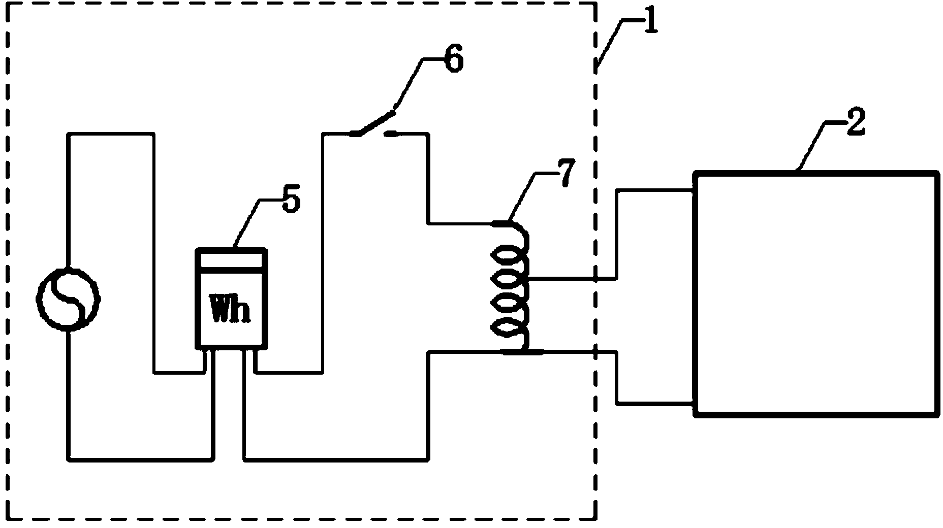
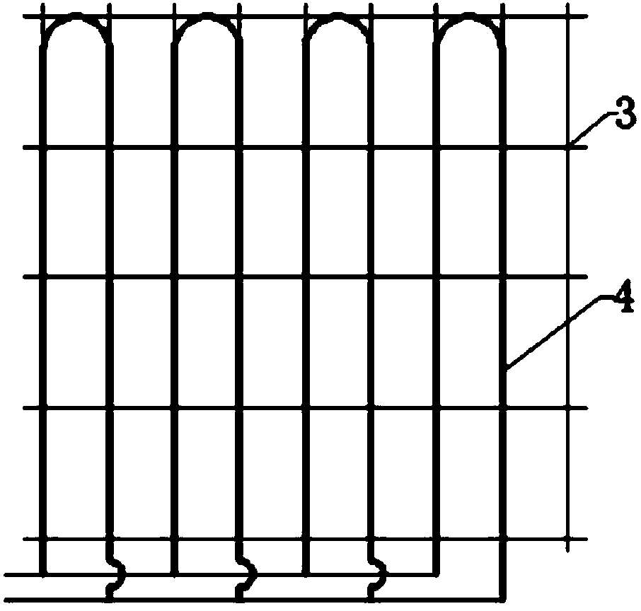
[0015] Such as figure 1 , 2 As shown, the airport asphalt concrete pavement heating system of the present invention includes an electric heating layer 2 located inside the airport asphalt concrete pavement, and a heating circuit 1 connected to the electric heating layer 2; the electric heating layer 2 includes steel wire mesh or geogrid The grid 3 and the carbon fiber heating wire 4 are arranged in a serpentine shape along the steel wire mesh or geogrid 3.

[0016] The spacing of the carbon fiber heating wires 4 is 4 cm to 15 cm.

[0017] The carbon fiber heating wire 4 includes carbon fiber threads, the surface of which is provided with a Teflon layer, the outer surface of the Teflon is covered with a protective film, and the outer surface of the protective film is covered with a stainless steel wire mesh.

[0018] The heating circuit 1 includes an electric energy meter 5, a manual switch 6 and an AC voltage regulator 7; the two input ends of the electric energy meter 5 are connecte...


PUM


Abstract

The invention provides a heating system for an airport bituminous concrete runway. The heating system is capable of quickly melting ice and snow, low in maintenance cost, safe and reliable. The heating system comprises an electric heating layer and a heating circuit, wherein the electric heating layer is located in the airport bituminous concrete runway, and the heating circuit is connected with the electric heating layer. The electric heating layer comprises a steel wire gauze or a geogrid and a carbon fiber heating wire, wherein the carbon fiber heating wire is arranged in a snakelike mode along the steel wire gauze or the geogrid. The heating system for the airport bituminous concrete runway can quickly and automatically melt the ice and snow on the airport bituminous concrete runway in winter, makes an airport operate normally in snowy weather, ensures safe taxiing, taking-off and landing of airplanes, and is low in construction cost, operating cost and maintenance cost, high in effective utilization rate of heat, friendly to the environment, economical, safe and reliable.

Description

Technical field [0001] The invention relates to an airport facility, in particular to an airport asphalt concrete pavement heating system. Background technique [0002] At present, airport asphalt concrete pavements in various countries around the world mainly use deicing agents to melt snow and ice, but deicing agents have many negative effects on airport asphalt concrete pavements and the surrounding environment, which are mainly manifested in the degradation of airport asphalt concrete pavement anti-aging performance , Decreased dynamic stability, corrosion of the drainage system, destruction of the surrounding soil ecological environment, and pollution of water sources. Other methods of snow melting and deicing include mechanical methods, which require a large number of personnel and snow shovel vehicles, and the deicing and snow removal effect is incomplete and severely delayed, which disrupts the normal operation of the airport. In addition, infrared-heated airport asphalt...

Claims


Application Information

Patent Timeline
Patent Type & Authority Applications(China)
IPC IPC(8): E01C11/26
Inventor 刘岩来勇马道迅
Owner CHINA AIRPORT CONSTR GRP
Learn More