Biomass particle suspension combustion boiler

A biomass particle, suspended combustion technology, applied in the field of boilers, can solve problems such as excessive fuel consumption, damage to driving equipment, slow water heating rate, etc., to increase the heat exchange area, increase the heat exchange time, and speed up the heating rate.

Inactive Publication Date: 2014-10-01
山东东工新能源科技有限公司
View PDF12 Cites 4 Cited by
  • Summary
  • Abstract
  • Description
  • Claims
  • Application Information

AI Technical Summary

Problems solved by technology

Although the heat of the flue gas has a certain heat exchange effect with the water around the flue gas channel when the flue gas runs along the flue gas channel, due to the fast running speed of the flue gas and the short stroke of the flue gas channel, most of the heat It is too late to exchange heat with water and discharge through the smoke outlet. At the same time, the water in the heating chamber is not separated, and all the water in the water storage chamber needs to be heated. Therefore, the high temperature in the flue gas channel in the existing boiler heating chamber The flue gas cannot fully contact with the water in the heating chamber, and the temperature of the water rises slowly, which leads to the defects of low boiler heat transfer efficiency and high fuel consumption. Moreover, the high-temperature flue gas contains a large amount of combustion ash. If the combustion ash is not cleaned in time, it will be It will have some side effects of heat insulation and blockage, so the convenience of cleaning the ash in the flue gas channel has become a key factor to improve the heat exchange efficiency of the boiler heating chamber
[0005] Most of the boilers currently in use do not have a waste heat recovery room, and generally cannot preheat the cold water added to the boiler, so cold water and hot water are mixed and heated in the boiler, the boundary between cold water and hot water is unclear, and the water temperature rises slowly. The heating effect is poor and the energy consumption is high. If the flue gas discharged through the smoke outlet is used to waste heat the cold water, not only the waste heat in the flue gas can be recovered, but also the heating effect of the boiler can be improved and the energy consumption of the boiler can be reduced.
The heat exchange device in the waste heat recovery chamber installed in the currently used boiler has poor heat exchange effect, resulting in poor effect and low efficiency of flue gas waste heat recovery, and a large amount of ash in the flue gas is easy to fall into the heat exchange device, and the It is not easy to clean, but if the ash is not cleaned in time, it will affect the efficiency of preheating recovery
[0006] When biomass pellets are used in boilers, the structural design of the air supply device and feeding device used in traditional boilers is unreasonable, and there are the following defects: 1. It cannot provide sufficient oxygen to meet sufficient carbon and oxygen mixing, and cannot adapt to biomass Combustion of particles; 2. Use the feeding device to send biomass particles directly into the combustion chamber, which will cause a large amount of biomass particles to accumulate in some areas of the combustion chamber, resulting in insufficient combustion of biomass particles; 3. The feeding device will continuously feed the biomass The material particles are sent into the combustion chamber, and the flame in the combustion chamber may flash back to the storage tank along the biomass particles, which poses a safety hazard; 4. When the biomass particle fuel is transported, the biomass particle fuel sometimes 5. The commonly used automatic ignition equipment is that the ignition rod injects flames into the combustion chamber. During the combustion process, the flame in the combustion chamber may flash back to the ignition rod and damage the ignition rod.

Method used


Image

  • Biomass particle suspension combustion boiler
  • Biomass particle suspension combustion boiler
  • Biomass particle suspension combustion boiler

Examples


specific Embodiment approach 1

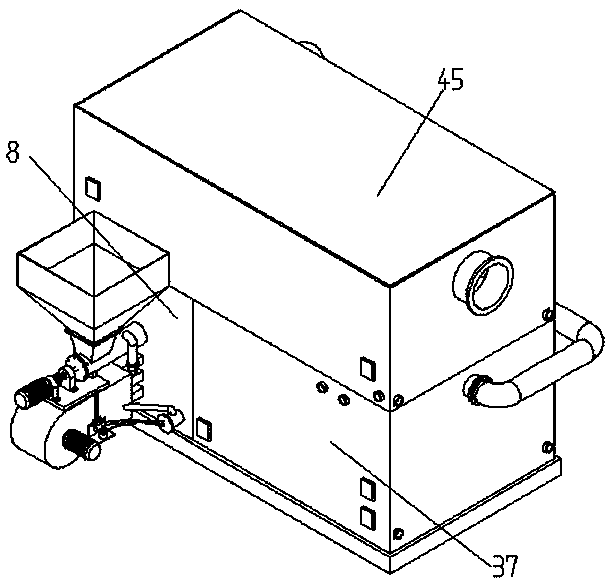
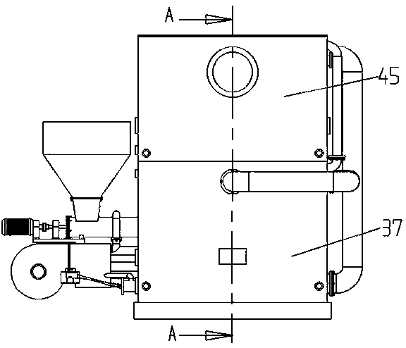
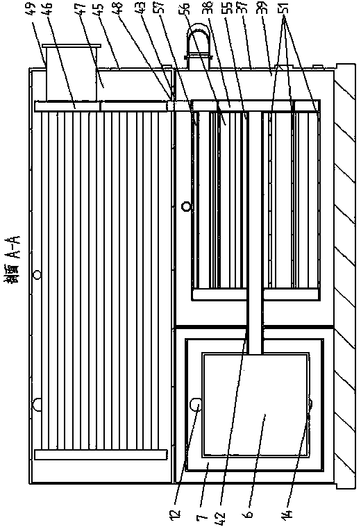
[0051] Such as Figure 1-4 , Figure 9 and Figure 14-18 As shown, a biomass particle combustion device for a boiler includes a combustion chamber 6, a feeding device, an air supply device and an automatic ignition device 28,

[0052] The air supply device includes a motor 1, a blower fan 4 driven by the motor 1, and a wind box 5 connected to the blower fan 4, and the top of the blower fan 4 and the blower box 5 is fixedly connected with a support plate 33;

[0053] The feeding device includes a motor 1 and a conveying auger 2 driven by the motor 1, the motor 1 is connected with the conveying auger 2 through a coupling 34, and a bracket 35 is also arranged between the motor 1 and the conveying auger 2 , the bracket 35 and the conveying auger 2 are fixed on the support plate 33, the top of the conveying auger 2 is provided with a storage hopper 3; the middle part of the conveying auger is provided with a vent 24, and the vent 24 The air duct 21 communicates with the air box ...

specific Embodiment approach 2

[0067] The difference with the above-mentioned specific embodiment 1 is: as Figure 5 As shown, the heat exchange device I38 includes four-stage heat exchange pipes I, and the four-stage heat exchange pipes I are arranged in a ring, and the first-stage heat exchange pipe I38.1 includes nine heat exchange pipes and is located in the The outermost periphery of the heat device I38, the second-stage heat exchange tube I38.3 includes seven heat exchange tubes, and the seven heat exchange tubes are evenly arranged inside the first-stage heat exchange tube I38.1, and the third-stage heat exchange tube I38.1 The heat pipe includes five heat exchange tubes, and the five heat exchange tubes are evenly arranged inside the second-stage heat exchange pipe I38.3, the fourth-stage heat exchange pipe I38.7 includes one heat exchange tube, and the fourth The first-stage heat exchange pipe I38.7 is located in the middle of the heat exchange device I38; the first-stage heat exchange pipe I38.1 c...

specific Embodiment approach 3

[0068] The difference with the specific embodiment 2 is: as Figure 6 and Figure 7 As shown, the heat exchange device I38 includes four-stage heat exchange pipes I, the four-stage heat exchange pipes I are connected in sequence, and arranged side by side and stacked in a matrix structure of 2X2, the smoke inlet I42 passes through the collection chamber I40 It is connected with the first-stage heat exchange pipe I38.1, and the first-stage heat exchange pipe I38.1 communicates with the second-stage heat exchange pipe I38.3 through the first-stage collection cavity I38.2, and the second-stage The heat exchange pipe I38.3 is arranged side by side on the side of the first heat exchange pipe I38.1, and the second heat exchange pipe I38.3 is connected with the third heat exchange pipe through the second heat exchange chamber I38.4 I38.5 are connected, the third-stage heat exchange pipe I38.5 is arranged side by side above the second-stage heat exchange pipe I38.3, and the third-sta...


PUM


Abstract

The invention relates to a biomass particle suspension combustion boiler. The biomass particle suspension combustion boiler comprises a combustion chamber, a heating chamber and a waste heat recovery chamber, wherein a smoke inlet I and a smoke outlet I are formed in the heating chamber, a water storage chamber I is arranged in the heating chamber, a heat exchange device I is arranged in the water storage chamber I, and the heat exchange device I comprises N (N is greater than or equal to 1) stage heat exchange pipes I; one end of a first stage heat exchange pipe I is communicated with the smoke inlet I, the other end of the first stage heat exchange pipe I is communicated with one end of a second stage heat exchange pipe I through a first stage gathering cavity I, the other end of the second stage heat exchange pipe I is communicated with one end of a third stage heat exchange pipe I through a second stage gathering cavity I and the like, and the other end of the N-1 heat exchange pipe I is communicated with one end of an N stage heat exchange pipe I through an N-1 stage gathering cavity I; the other end of the N stage heat exchange pipe I is communicated with the smoke outlet I, a dust removing opening I is formed in the first gathering cavity I and / or part or all of the other gathering cavities I, and the dust removing opening I is communicated with the shell of the heating chamber.

Description

technical field [0001] The invention relates to the technical field of boilers, in particular to a biomass particle suspension combustion boiler. Background technique [0002] Biomass pellets produced by herbaceous and woody organisms are high-quality biomass fuels. At present, my country has basically solved the problem of transforming crop straws and other materials into biomass pellets. Biomass pellets can be used to replace coal, fuel oil and natural gas. It not only has the characteristics of high combustion efficiency and less pollution emissions, but also its price is far lower than fuel oil, not higher than coal and natural gas, so biomass pellets are more suitable for boilers usage of. However, because biomass particles objectively have the characteristics of low carbon content, high ash and volatile content, in the combustion process, compared with coal or fuel oil, more sufficient oxygen and a more uniform carbon-oxygen balance space are required, otherwise it wi...

Claims


Application Information

Patent Timeline
Patent Type & Authority Applications(China)
IPC IPC(8): F23C10/00F23C10/18F23C10/20F23C10/22
Inventor 李守涛
Owner 山东东工新能源科技有限公司
Why Eureka
Try Eureka