An optical image enhancement device and method

An image enhancement and image signal technology, applied in optics, nonlinear optics, instruments, etc., can solve the problems of inability to prepare crystals and no image enhancement, and achieve the effect of increasing the gain.

Active Publication Date: 2017-02-08
TECHNICAL INST OF PHYSICS & CHEMISTRY - CHINESE ACAD OF SCI
View PDF5 Cites 0 Cited by
  • Summary
  • Abstract
  • Description
  • Claims
  • Application Information

AI Technical Summary

Problems solved by technology

Due to the limitations of the technology at that time, usable crystals could not be prepared
But there is no report on image enhancement based on QPM

Method used


Image

  • An optical image enhancement device and method
  • An optical image enhancement device and method
  • An optical image enhancement device and method

Examples


Embodiment 1

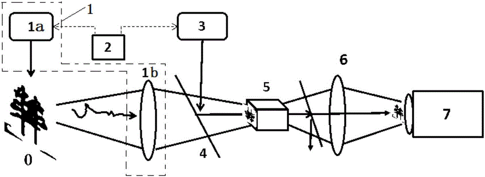
[0038] Such as figure 1 As shown, the present invention provides an optical parametric image enhancement device, which includes a signal light laser emitting module (1a) and a signal light laser receiving module (1b), and the signal light laser emitting module (1a) and a signal light laser receiving module The module (1b) consists of a signal light laser emitting and receiving module (1), a synchronous control module (2), a pump laser module (3), a signal light and pump light coupling module (4), a quasi-phase matching frequency conversion crystal and its Adjustment module (5), image signal selection module (6) and imaging module (7), wherein:

[0039] The signal light laser emitting and receiving module (1), used for generating and emitting signal light laser, and receiving the image signal returned from the imaging target (0);

[0040] The synchronous control module (2) is used to control the pump laser module (3), so that the pump laser and the image signal pass through th...

Embodiment 2

[0064] refer to Figure 6 , this embodiment proposes an optical image enhancement device based on quasi-phase matching with the pump light at 355 nm and the signal light at 532 nm.

[0065] Among them, the signal light laser emitting and receiving module (1) is composed of a 532nm picosecond laser generated by frequency doubling of a fundamental frequency laser with a wavelength of 1064nm, and the pump laser module (3) is composed of a laser from the same fundamental frequency 1064nm laser source through The picosecond laser with a wavelength of 355nm generated by triple frequency is composed of a picosecond laser with a wavelength of 355nm. Due to the relatively short detection distance, the synchronization control module (2) is only composed of an optical delay. Module (2) adjusts the stroke of the pump laser to make the two equal.

[0066] This embodiment adopts transmission imaging, the signal light emitted by the signal laser (100) passes through the target (0) After th...

Embodiment 3

[0070] Such as Figure 7 As shown, this embodiment proposes a device for optical image enhancement based on quasi-phase matching with the pump light at 355 nm and the signal light at 1064 nm.

[0071] The pump laser in this embodiment is the same as that in Embodiment 2; MgO:PPSLT is also used as the quasi-phase-matched crystal for 355nm pumping. The parameters of the MgO:PPSLT crystal are as follows: the length is 20 mm, the period is 6.6 μm, and the effective nonlinear coefficient is 6.7 pm / V, the transparent surface is 5×8mm2. The signal light incident end is coated with 355nm and 1064nm anti-reflection coatings; the output end is coated with 355nm and 532nm anti-reflection coatings.

[0072] The signal light laser emitting and receiving module (1) is composed of Nd:YAG fundamental frequency laser with a wavelength of 1064nm, and the pulse width is 100ns. The pump laser module (3) is three times The nanosecond laser with a wavelength of 355nm generated at a high frequency...


PUM

PropertyMeasurementUnit
lengthaaaaaaaaaa

Abstract

The invention provides an optical parameter image enhancement device based on quasi-phase matching. A signal light laser transmitting and receiving module (1) is used for generating and transmitting signal light laser and receiving an image signal returned from an imaging object (0). A synchronous control module (2) is used for controlling a pump laser module (3) to allow pump laser and the image signal to pass a signal light and pump light coupling module (4) at the same time and to enter a quasi-phase matching frequency-changer crystal and regulating module (5). The quasi-phase matching frequency-changer crystal and regulating module (5) is used for allowing the pump light and the image signal to engage in quasi-phase matching. An output image is an enhanced signal light image and / or a newly-generated conjugated idling-frequency light image. The characteristic of maximum nonlinear coefficient of a nonlinear medium is made full use by quasi-phase matching, gain of the optical image is significantly improved, and detection of weak image signals is favored.

Description

technical field [0001] The invention relates to the technical field of optical image enlargement, in particular to an optical image enhancement device and method. Background technique [0002] Optical parametric image enhancement technology is an important application direction of Optical Parametric Amplification (OPA) technology. With its advantages of high optical gain, high-precision time gating, and frequency up-conversion, it is widely used in laboratory biology and medicine , Chemical analysis and ultrafast imaging process research have achieved important applications; at the same time, it also has great application value in lidar, optical remote sensing, and quantum imaging. [0003] At present, optical parametric image intensification devices all use conventional phase matching technology to achieve phase matching between signal light and pump light. However, conventional phase matching technology represented by critical phase matching requires strict angle or temper...

Claims


Application Information

Patent Timeline
Patent Type & Authority Patents(China)
IPC IPC(8): G02F1/39G02F1/37G02F1/355
Inventor 杨晶李小青彭钦军许祖彦张景园
Owner TECHNICAL INST OF PHYSICS & CHEMISTRY - CHINESE ACAD OF SCI
Why Eureka
Try Eureka