
Cable fault detection and aging analysis method

A cable fault and aging analysis technology, applied in the direction of fault location, etc., can solve the problems of measurement accuracy impact, long sweep time, large fault location error, etc., and achieve the effect of reducing the volume of test equipment, saving test time, and accurate fault location

Active Publication Date: 2014-10-08
GAUSS ELECTRONICS TECH
View PDF4 Cites 38 Cited by
  • Summary
  • Abstract
  • Description
  • Claims
  • Application Information

AI Technical Summary

Problems solved by technology

However, the disadvantage of FDR is that the sweeping time is long, and the measurement accuracy is affected by the stepping frequency of the sweeping frequency. That is, the longer the cable, the more sweeping points are, and the longer the test time is. the greater the error
At present, the frequency sweep frequency band and frequency sweep step used for FDR mainly depend on the experience of the testers. Therefore, the hardware structure of the FDR method is more complicated than that of the TDR method, and different measurement results (positioning errors) are obtained due to the difference in operator experience. And FDR is difficult to estimate for cables of unknown length
Therefore, the promotion and application of FDR is limited
[0005] The use of non-destructive test analysis methods has gradually become popular in recent years, but the current analysis methods based on TDR and FDR not only face the above problems, but also can only be used for the analysis of cable fault points, and cannot provide direct analysis results for the cable insulation aging state

Method used


Image

  • Cable fault detection and aging analysis method
  • Cable fault detection and aging analysis method
  • Cable fault detection and aging analysis method

Examples


Embodiment 1

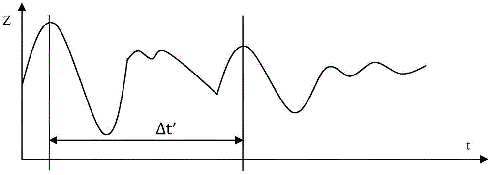
[0065] Such as figure 1 , figure 2 , image 3 shown. Fault detection and aging analysis for 220kV and XLPE cables include the following steps.

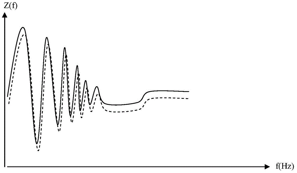
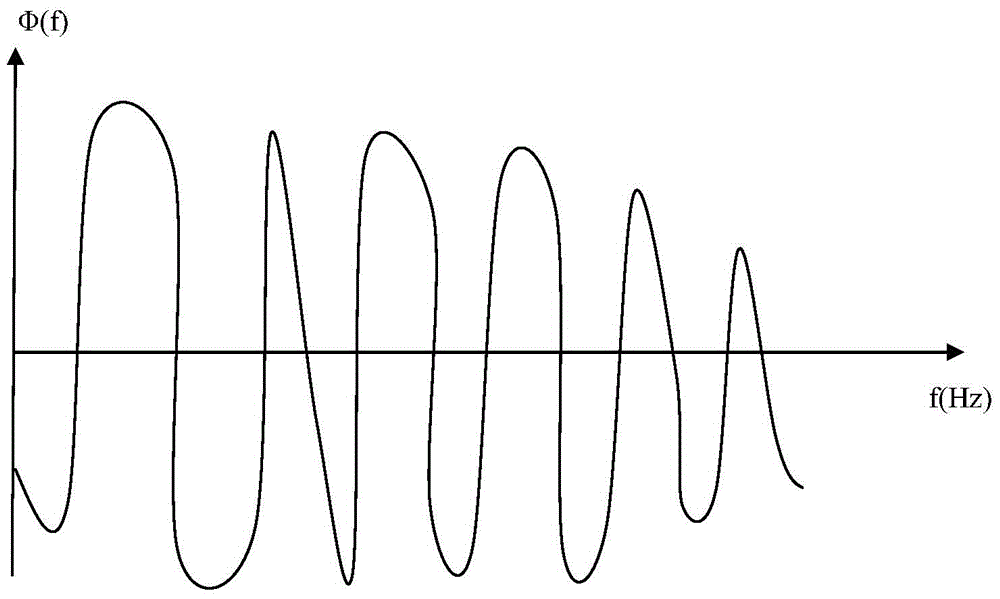
[0066] The first step is to apply a bandwidth of 0.1Hz-10kHz and a step frequency Δf between the insulated conductor and the shielding layer of the tested cable in the no-load state. k It is a 20Hz sweep signal, and then collect the voltage time domain signal corresponding to each sweep frequency input signal and the current time domain signal flowing through the cable to form a loop, and calculate the frequency domain impedance and phase of the cable, and draw the continuous impedance frequency curves and phase-frequency curves such as figure 1 , figure 2 shown.

[0067] In the second step, on the impedance frequency curve drawn in the first step, find the first impedance peak value Z 0 is 400Ω, and its corresponding frequency f 0 The oscillation cut-off frequency f corresponding to the minimum impedance value of 320Hz and ...

Embodiment 2

[0081] Such as Figure 4 , Figure 5 shown. Fault detection and aging analysis for 220kV, XLPE cables with unknown length, including the following steps.

[0082] The first step is to apply a bandwidth of 100Hz-10kHz and a step frequency Δf between the multi-core cable conductors of the cable under load. k It is a 100Hz sweep signal, and then collect the voltage time domain signal corresponding to each sweep frequency input signal and the current time domain signal flowing through the cable to form a loop, and calculate the frequency domain impedance and phase of the cable, and draw the continuous impedance frequency curves and phase-frequency curves such as Figure 4 , Figure 5 shown.

[0083] In the second step, on the impedance frequency curve drawn in the first step, find the frequency f corresponding to the first impedance peak 0x The oscillation cut-off frequency f corresponding to the minimum impedance value of 206Hz and oscillation amplitude attenuation dx is 1...

Embodiment 3

[0099] The same parts as in Embodiment 2 will not be described again, the difference is that fault detection and aging analysis are performed on a 450kV cable with an unknown insulation type and a length of 10m. Pre-calculate the impedance-frequency curve of the cable, the initial sweep frequency point of the phase-frequency curve, the highest value of the sweep frequency, and the step value of the sweep frequency to optimize the test frequency band and improve test efficiency.

[0100] As stated earlier in this specification, the shorter the cable length, the higher the test frequency should be. First estimate the starting frequency range of the cable test, and set the transmission rate as half of the speed of light, that is, 150×10 6 m / s, then the characteristic frequency corresponding to the 10m far end of the cable is Assuming that the minimum detectable starting point (fault point and test terminal) distance is 0.1m, then the detected fault distance error is also 0.1m, ...


PUM

PropertyMeasurementUnit
Lengthaaaaaaaaaa

Abstract

The invention discloses a cable fault detection and aging analysis method. According to the insulation resistance oscillation theory of the frequency domain, the cable fault detection and aging analysis method is characterized in that a fault location model is established by analyzing the oscillation characteristics of frequency domain impedance on the basis of oscillation wave spectrum analysis of the frequency domain impedance acquired by a non-destructive test system or a destructive test system, and then test oscillation impedance spectrum defect is compared with an internal simulation curve, so that long-distance accurate fault location can be realized, and the fault types can be also effectively distinguished. Compared with the prior art, the method not only is capable of realizing accurate multipoint positioning of faults, but also is capable of carrying out fault type recognition and insulation aging state analysis; in the whole detection and analysis processes, artificial experience is hardly depended; the method is suitable for a cable with the length of 1m-1,000km, and is especially suitable for a cable with the length of more than hundreds of kilometers.

Description

technical field [0001] The invention relates to a cable fault detection and aging analysis method, in particular to a fault detection and aging analysis method applicable to cables with a distance of 1m-1000km, especially hundreds of kilometers. Background technique [0002] Cables are indispensable power equipment in the development of industrial and civil industries. They are widely used in power transmission, control signal transmission and communication systems. Therefore, maintaining and testing cables has become an essential work to ensure power systems, communication systems and control equipment. At present, there are mainly TDR positioning method and FDR analysis method for cable fault detection. [0003] The TDR positioning method mainly applies a low-voltage non-destructive DC pulse signal to the cable, then collects the reflected signal from the cable, calculates the time difference between the DC pulse signal application time point T1 and the reflected signal ap...

Claims


Application Information

Patent Timeline
IPC IPC(8): G01R31/08
Inventor 张建尹娟张方荣高兴琼
Owner GAUSS ELECTRONICS TECH
Learn More