Inelastic collision and rolling viscous resistance particle coupling energy dissipation cutter rod

A technology of inelastic collision and viscous resistance, applied in the direction of boring bars, etc., can solve the problems of restricting the boring processing of deep-hole parts, the deterioration of machining accuracy and surface quality, and the inability to increase the diameter of the tool, and achieve small structural changes. , Improve the stability and accuracy, the effect of vibration suppression effect is obvious

Active Publication Date: 2014-10-15
厦门粒资科技有限公司
View PDF7 Cites 3 Cited by
  • Summary
  • Abstract
  • Description
  • Claims
  • Application Information

AI Technical Summary

Problems solved by technology

However, for tool holders with a length-to-diameter ratio of more than 4 times, the effect of this method is not obvious, especially in the case of complex tool structures, the cost is very high, and due to the limitation of the size of the workpiece to be processed, it cannot be enlarged in many cases. Tool diameter, so improving the static stiffness of the tool has certain application limitations
In addition, reducing the amount of cutting to reduce the cutting force can reduce t...

Method used


Image

  • Inelastic collision and rolling viscous resistance particle coupling energy dissipation cutter rod
  • Inelastic collision and rolling viscous resistance particle coupling energy dissipation cutter rod
  • Inelastic collision and rolling viscous resistance particle coupling energy dissipation cutter rod

Examples


Embodiment Construction

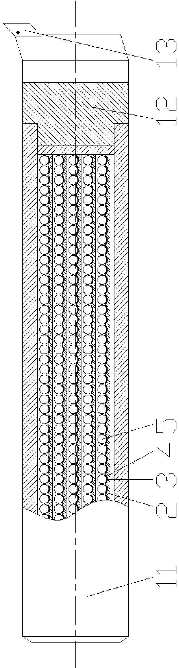
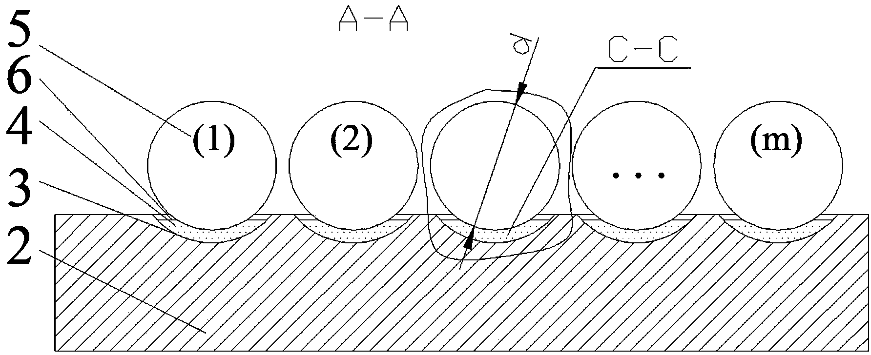
[0027] see Figure 1-7 , the embodiment of the present invention is provided with a cutter bar body 11, a cutter bar connector 12, a cutter head 13, and a coupling energy dissipation plate 2; a groove array is provided on the coupling energy dissipation plate 2, and each groove of the groove array 3 is provided with one surface low restitution coefficient particle 5 and at least two high surface viscous resistance polymer particles 4, the surface of the high surface viscous resistance polymer particle 4 is coated with a high polymer film 6, and the coupling energy dissipation plate 2 is provided with a fixing slot 7 for installing a coupling energy dissipation board.

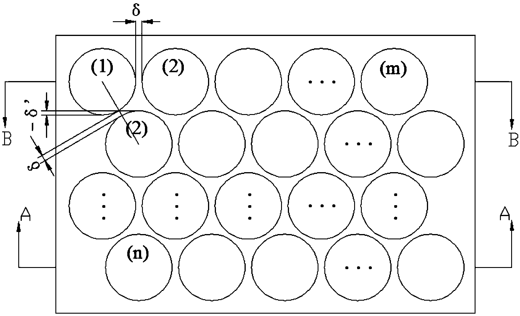
[0028] The groove array can be set as an m×n groove array, m is the number of particle grooves in the longitudinal direction of the coupling energy dissipation plate 2 , and n is the number of particle grooves in the width direction of the coupling energy dissipation plate 2 .

[0029] The high surface viscous ...


PUM

PropertyMeasurementUnit
Particle sizeaaaaaaaaaa
Thicknessaaaaaaaaaa
Densityaaaaaaaaaa

Abstract

An inelastic collision and rolling viscous resistance particle coupling energy dissipation cutter rod relates to a cutting tool. The cutter rod comprises a cutter rod body, a cutter rod connection piece, a cutting head and coupling energy dissipation plates. A groove array is formed in each coupling energy dissipation plate. A surface low recovery coefficient particle and at least two high surface viscous resistance macromolecule particles are arranged in each groove, a high polymer film wraps the surface of each high surface viscous resistance macromolecule particle, and a fixed groove for installing the coupling energy dissipation plate is formed in each coupling energy dissipation plate. After multiple layers of coupling energy dissipation plates are installed in the cutter rod, vibration energy generated by cutting force can be dissipated quickly and gradually, energy dissipation factors are high, the vibration restraining effect is obvious, and boring stability and accuracy of parts with deep holes are effectively improved. The cutter rod is low in cost and easy to implement. The surface low recovery coefficient particles utilize a metal material as the base material, methyl phenyl polysiloxane and acrylate interpenetration polymer wraps the base material, and the surface low recovery coefficient particles are high in strength, not prone to corrosion, long in service life and capable of being used in a long term.

Description

technical field [0001] The invention relates to a cutting tool, in particular to a non-elastic collision and rolling viscous resistance particle coupled energy-dissipating tool holder. Background technique [0002] In machining, deep hole machining has always been a difficult problem. During the boring process, when the length-to-diameter ratio of the tool bar exceeds 4 times, the tool itself will vibrate under the action of cutting force, which will reduce the machining accuracy and even make it impossible to process. [0003] Most domestic anti-vibration cutting tools are in the research stage, and the method adopted (see Chinese patent 200920061678.5) is mainly to increase the static stiffness of the tool holder, such as nickel-based heavy alloy anti-vibration cutting tools. However, for tool holders with a length-to-diameter ratio of more than 4 times, the effect of this method is not obvious, especially in the case of complex tool structures, the cost is very high, and...

Claims


Application Information

Patent Timeline
IPC IPC(8): B23B29/02
CPCB23B29/022
Inventor 肖望强
Owner 厦门粒资科技有限公司
Why Eureka
Try Eureka