Field emission ionization source for time-of-flight mass spectrometer

A technology of time-of-flight mass spectrometry and field emission, which is applied in the field of electron impact ionization sources, and can solve problems such as difficulties

Active Publication Date: 2014-10-15
PEKING UNIV
View PDF6 Cites 6 Cited by
  • Summary
  • Abstract
  • Description
  • Claims
  • Application Information

AI Technical Summary

Problems solved by technology

[0005] In summary, the use of field emission ionization source technology in miniaturized TOF-MS instruments has obvious advantages, but also has great practical difficulties
How to solve the problems of field emission current, lifetime, and stability, and how to adjust the energy of electrons to make it suitable for the impact ionization of gas molecules without losing electrons as much as possible are technical problems that have not been well resolved.

Method used


Image

  • Field emission ionization source for time-of-flight mass spectrometer
  • Field emission ionization source for time-of-flight mass spectrometer
  • Field emission ionization source for time-of-flight mass spectrometer

Examples


Embodiment 1

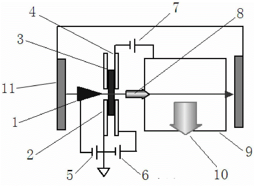
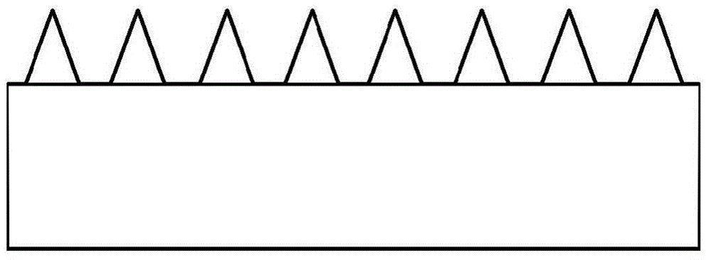
[0024] The following is a realization method of a miniature TOF-MS ionization source based on blade-shaped cathode field emission. use figure 2 As shown in the "serrated blade" cathode emitter 1, the cathode emitter 1 has a width of 10 mm and a thickness of 0.1 mm. The radius of curvature of all tips on the cathode emitter 1 is less than 100 nm, and the spacing is 20-50 microns. The metal cathode of this shape can be used directly, or a layer of nanomaterials (such as carbon nanotubes) can be attached to its tip. The slit width of the anode slit electrode 2 is 0.2-0.8 mm, and the slit length is 12 mm. The distance between cathode and anode is adjustable from 2-100 microns. The output electrode of the microchannel plate (that is, the MCP slit electrode) and the corresponding slit on the ionization box have a width of 0.8-1.2 mm and a length of 12 mm. All electrodes are machined from non-magnetic stainless steel sheets with a thickness of 0.5 mm. A 200-1000 Gauss magnetic f...

Embodiment 2

[0027] The following is a realization method of a miniature TOF-MS ionization source based on planar cathode field emission. A mixture of single-wall carbon nanotubes and titanium dioxide nanoparticles (titanium dioxide accounts for about 7% of the total weight) was wipe-coated on the surface of a frosted copper sheet as a cathode emitter by mechanical wiping. Fix the cathode copper sheet to an electrode sheet. Then align the cathode emitter with the anode slit electrode, and connect the anode slit electrode with ceramic sheets and nylon screws. The width of the anode slit is 0.2-0.8 mm, and the length of the slit is 12 mm. By adjusting the thickness of the ceramic sheet, the distance between the cathode and the anode is 20-100 microns. The output electrode of the microchannel plate (that is, the MCP slit electrode) and the corresponding slit on the ionization box have a width of 0.8-1.2 mm and a length of 12 mm. All electrodes are machined from non-magnetic stainless steel...


PUM


Abstract

The invention provides a field emission ionization source for a time-of-flight mass spectrometer. The field emission ionization source aims at solving the problems that a glow wire of a glow wire emission electron collision ionization source has high energy consumption and high-temperature thermal desorption, and cannot be miniaturized. The field emission ionization source adopts the technical scheme that a blade coated with a nanomaterial or a planar electrode directly coated with the nanomaterial serves as a cold cathode emitter; an anode is in a slit structure; a microchannel plate component is designed behind a slit of the anode, and used for amplifying electron current and adjusting electron energy; and finally an electron beam with appropriate energy strikes an ionization box to ionize gas molecules under magnetic field constraint. Therefore, a field emission cathode can operate at lower voltage and is not easy to damage, and the electron energy striking the ionization box can be independently controlled to be more suitable for ionizing the gas molecules. In an application, pulsed ionization can be achieved only by applying pulsed negative high voltage on the cathode, so that a pulsed flaky ion beam is generated for perpendicular lead-out and detection analysis.

Description

technical field [0001] The invention relates to an electron impact ionization source, mainly relates to the working principle and related technology of using field emission electrons to impact ionized gas molecules to generate ions, and particularly relates to the technical approach of using the ionization source in a time-of-flight mass spectrometer. Background technique [0002] The ionization source is a device that ionizes free gas molecules or bound atoms (atomic groups) on the solid surface to generate free ions. It is one of the core devices of a mass spectrometer. The ionization source technologies currently used in mass spectrometry instruments include hot filament emitted electron impact ionization, pulsed laser ionization, ultraviolet photoionization, electrospray ionization, and Penning discharge ionization. In time-of-flight mass spectrometer (TOF-MS), the hot filament emits electron impact ionization and pulsed laser ionization technologies are most widely used...

Claims


Application Information

Patent Timeline
Patent Type & Authority Applications(China)
IPC IPC(8): H01J49/16
Inventor 郭等柱胡秋宁
Owner PEKING UNIV
Why Eureka
Try Eureka