Composite diaphragm for battery and preparation method thereof

A composite membrane and battery technology, applied in the field of electrochemical batteries, can solve the problems of unstable interface between electrolyte and electrode material, slow ion transmission, battery performance degradation, etc., to alleviate uneven corrosion, improve high-current charge-discharge performance, The effect of reducing internal resistance

Inactive Publication Date: 2014-10-15
INST OF METAL RESEARCH - CHINESE ACAD OF SCI
View PDF13 Cites 72 Cited by
  • Summary
  • Abstract
  • Description
  • Claims
  • Application Information

AI Technical Summary

Problems solved by technology

Although the solid electrolyte separator can greatly reduce the electrochemical corrosion of the electrolyte to the metal lithium electrode, the ion transmission speed is very slow, and the ion conductivity is very low. It needs a higher temperature to have a faster ion migration speed to achieve

Method used


Image

  • Composite diaphragm for battery and preparation method thereof
  • Composite diaphragm for battery and preparation method thereof
  • Composite diaphragm for battery and preparation method thereof

Examples


Embodiment 1

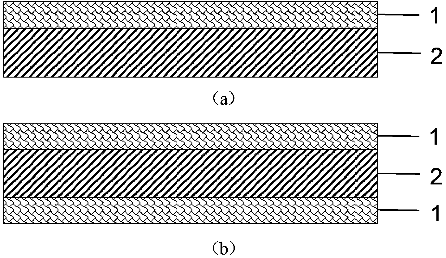
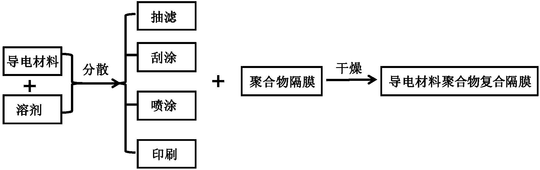
[0038] Add 100mg of graphene into 200mL ethanol and disperse uniformly by ultrasonic for 0.5h (the content of graphene in the dispersion is 0.5mg / mL) and filter it onto the continuously rolling polypropylene microporous diaphragm to form a strip-shaped composite diaphragm. After drying under vacuum for 12 hours to remove the solvent, a composite diaphragm of graphene film layer and polymer layer (polypropylene microporous diaphragm) can be obtained. The composite diaphragm is shown in image 3 (a) (shown in the lower part), the graphene-polypropylene composite diaphragm is sliced ​​and the photo is shown in image 3 (b). The scanning electron microscope picture of the graphene thin film layer in the obtained composite separator is shown in Figure 4 (a-b), it can be seen that the graphene sheets are tightly stacked, and the lateral size of graphene is 5-50 microns.

[0039] Figure 5 In order to test the lithium iron phosphate cathode material in the lithium-ion battery, th...

Embodiment 2

[0043] The graphene in Example 1 was replaced by a composite of multi-walled carbon nanotubes and conductive carbon black. After being uniformly dispersed in NMP, a PP diaphragm with a thickness of 20 μm and a pore diameter of 100 nm was formed on one side with a thickness of A conductive layer of 2 μm constitutes a composite separator for testing the battery performance of the lithium iron phosphate cathode material, and can obtain battery performance similar to that of Example 1, and is obviously better than that of Comparative Example 1.

Embodiment 3

[0045] Replace the graphene in Example 1 with a composite of mesoporous carbon and microporous carbon spheres. After uniform dispersion in DMF, use the method of scraping to form a thickness of A conductive layer of 5 μm constitutes a composite separator for testing the battery performance of the lithium iron phosphate positive electrode material. The battery performance similar to that of Example 1 can be obtained, and it is obviously better than the battery performance of Comparative Example 1.


PUM

PropertyMeasurementUnit
Thicknessaaaaaaaaaa
Conductivityaaaaaaaaaa
Thicknessaaaaaaaaaa

Abstract

The invention discloses a composite diaphragm for a battery and a preparation method thereof, belonging to the field of electrochemical cells. The composite diaphragm is a multilayer composite diaphragm structure composed of a conducting layer/a polymer layer or a conducting layer/a polymer layer/a conducting layer, wherein the conducting layer mainly comprises a carbon material or a conductive polymeric material and forms a film on a single surface or double surfaces of a polymer diaphragm. The composite diaphragm has the following characteristics: the conducting layer has strong electrolyte adsorption and storage capability, the process of ion transport is shortened, and large-current charge and discharge performance of the battery is improved; when the composite diaphragm is used in a metallic lithium battery, the conducting layer in the composite diaphragm contacting with metallic lithium can alleviate nonuniform corrosion on the surface of lithium and inhibit formation of lithium dendrite crystals. The preparation method for the composite diaphragm is simple and easily controllable, can realize large-quantity and low-cost industrial preparation of the composite diaphragm and has a high application value.

Description

technical field [0001] The invention belongs to the technical field of electrochemical batteries, and in particular relates to a battery composite diaphragm and a preparation method thereof. Background technique [0002] Separator is an important part of various batteries. Its main function is to separate the positive and negative active materials of the battery, prevent the short circuit caused by the contact between the two poles, and allow the ions in the electrolyte to pass through. For the diaphragm, it needs to have good wettability to the electrolyte, high liquid absorption rate, which is beneficial to improve the ionic conductivity, and has good chemical stability. It cannot chemically react or dissolve with the electrolyte in the solvent system. In order to ensure assembly, it is required to have a relatively High tensile strength and puncture strength meet the winding assembly process. At the same time, in order to ensure safety, higher porosity is required to incr...

Claims


Application Information

Patent Timeline
IPC IPC(8): H01M2/16H01M50/403H01M50/417H01M50/44H01M50/457H01M50/489H01M50/491H01M50/497
CPCH01M50/403H01M50/449Y02E60/10
Inventor 李峰周光敏裴嵩峰李璐黄坤成会明
Owner INST OF METAL RESEARCH - CHINESE ACAD OF SCI
Why Eureka
Try Eureka