Aurora activity monitoring system

An activity monitoring and Aurora technology, applied in the field of environmental data, can solve problems such as difficult synchronization, high transportation costs, time and file generation time differences, etc., and achieve the effect of high cost performance, simple maintenance, and small size

Active Publication Date: 2014-10-22
POLAR RES INST OF CHINA
View PDF6 Cites 1 Cited by
  • Summary
  • Abstract
  • Description
  • Claims
  • Application Information

AI Technical Summary

Problems solved by technology

[0007] 1. The camera itself is bulky and needs to be installed outdoors or under a special transparent cover, with little mobility;
[0008] 2. The adjustment of the controller's gain, sensitivity and number of superimposed frames needs to be done manually, and all the above parameters start from the minimum value before each observation, and gradually adjust to the appropriate imaging quality, and restore each parameter to the minimum after the observation value, the adjustment process takes a long time
In each observation process, after the parameters are relatively fixed, the ideal observation of weak aurora and strong aurora cannot be realized at the same time for the strong dynamic range during the auroral activity;
[0009] 3. Light-controlled shutdown and timing shutdown cannot be achieved. Someone must be on duty during the observation process to avoid fatal damage to the camera due to strong light after sunrise;
[0010] 4. Video digitization is difficult. Although the video signal after the time base corrector can be introduced to the computer installed with the video capture card to regularly collect digital images, it is difficult to synchronize the time on the clock generator with the time on the computer, resulting in image There is a discrepancy between the above time and the file generation time;
[0011] 5. The video image resolution is not high, and the maximum resolution of video digital output is only 320×240 pixels;
[0012] 6. The online real-time video

Method used


Image

  • Aurora activity monitoring system
  • Aurora activity monitoring system
  • Aurora activity monitoring system

Examples


Embodiment Construction

[0038] The technical solutions of the present invention will be further described below in conjunction with the accompanying drawings and through specific implementation methods.

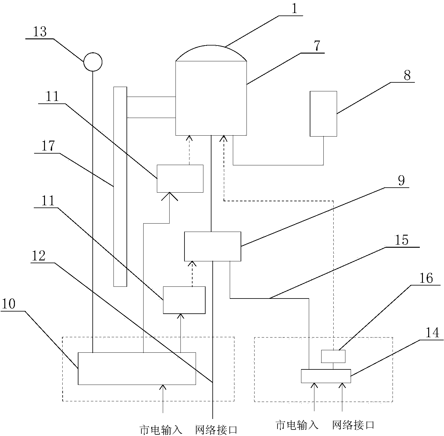
[0039] image 3 It is a structural schematic diagram of an aurora activity monitoring system provided by a specific embodiment of the present invention. Such as image 3 As shown, a kind of aurora activity monitoring system described in the present invention includes: a fisheye lens 1 for aurora full-sky imaging, a low-illuminance industrial camera 7 for aurora full-sky imaging to generate aurora analog video signals, Control the camera controller 8 of low-illuminance industrial camera 7, and be used for converting aurora analog video signal into digitized video and provide the video encoder 9 of online video stream function for the outside world by being connected with network, described fisheye lens 1 is installed on The front end of the low-illuminance industrial camera 7, the low-illuminance i...


PUM


Abstract

The invention relates to an aurora monitoring system. The aurora monitoring system comprises a fish-eye lens for aurora full-sky imaging, a low-light industrial camera for converting the aurora full-sky imaging into an aurora analog video signal, a camera controller for controlling the low-light industrial camera, and a video encoder for converting the aurora analog video signal into a digital video and providing the outside with an online video streaming function by connecting the digital video with a network, wherein the fish-eye lens is installed at the front end of the low-light industrial camera, the low-light industrial camera is connected with the video encoder through a bayonet nut connector (BNC) cable, and the camera controller is electrically connected with the low-light industrial camera. According to the aurora monitoring system, good aurora imaging is achieved under an extreme weak light condition, the online video streaming function can be provided, automatic unattended observation is achieved, and the aurora monitoring system has the advantages of being convenient to install and operate, low in cost, good in imaging quality, and capable of performing on-line video streaming output, timing image capture, and meeting requirements of aurora activity real-time monitoring.

Description

technical field [0001] The invention relates to the technical field of environmental data, in particular to an aurora activity monitoring system. Background technique [0002] Aurora is an atmospheric luminescence phenomenon in the polar region produced by the interaction of solar wind plasma generated by solar activities and the earth's atmosphere. It is an important indicator of disastrous space weather activities that affect the operation of artificial satellites, space stations and the safety of human space activities. important target audience of the research. The sun-earth system on which human beings depend, along with the activities of the sun, can monitor the changes in the space environment such as changes in the geomagnetic field and ionospheric disturbances in earth space through special instruments and equipment, and the aurora is the only high-altitude atmospheric physics that can be seen by the naked eye. The phenomenon has long been paid attention to in the ...

Claims


Application Information

Patent Timeline
IPC IPC(8): H04N7/18H04N5/232
Inventor 黄德宏胡红桥胡泽骏
Owner POLAR RES INST OF CHINA
Why Eureka
Try Eureka