
Horizontal fire tube boiler with gas-gas heat tube heat exchange tube arranged on tail

A fire tube boiler and gas heat pipe technology, applied in the field of heating equipment, can solve the problems such as the inability of the flue gas to reach the dew point temperature, the inability to condense the water vapor, and the maintenance and replacement of the boiler, so as to reduce the fuel consumption of the boiler and the compact structure of the boiler. , the effect of saving space

Inactive Publication Date: 2014-10-29
JIANGSU SHUANGLIANG BOILER
View PDF6 Cites 1 Cited by
  • Summary
  • Abstract
  • Description
  • Claims
  • Application Information

AI Technical Summary

Problems solved by technology

[0003] At present, the heating surface at the tail of the boiler on the market is mostly in the form of a serpentine tube and an extended heating surface to increase the heating area, and to reduce the exhaust gas temperature of the boiler in the form of heat exchange between the flue gas and the boiler water, but for a part of the hot water used for heating For users of boilers and steam condensate recovery steam boilers, when the return water temperature of the hot water boiler and the water temperature of the condensate recovery of the steam boiler are as high as 60-70°C, the exhaust gas temperature at the tail of the boiler reaches 80-90°C. At this time, the flue gas cannot Below the dew point temperature, the water vapor in the flue gas cannot be condensed
And as long as one of the heating surfaces at the tail of the ordinary serpentine tube is damaged, the furnace must be shut down for inspection and replacement.

Method used


Image

  • Horizontal fire tube boiler with gas-gas heat tube heat exchange tube arranged on tail
  • Horizontal fire tube boiler with gas-gas heat tube heat exchange tube arranged on tail
  • Horizontal fire tube boiler with gas-gas heat tube heat exchange tube arranged on tail

Examples


Embodiment Construction

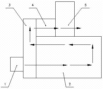
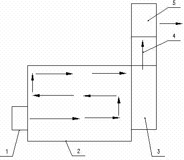
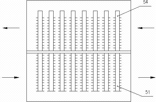
[0027] See figure 1 with figure 2 , figure 1 In order to invent the flow diagram of a horizontal fire tube boiler with a gas-gas heat pipe heat exchanger at the end of the three-pass. figure 2 In order to invent the flow diagram of a horizontal fire tube boiler with a gas-gas heat pipe heat exchanger at the end of the second pass. by figure 1 with figure 2 It can be seen that the horizontal fire tube boiler with gas-gas heat pipe heat exchange tube at the tail of the present invention is mainly composed of burner 1, boiler body 2, turning smoke chamber 3, economizer 4, and gas-gas heat pipe heat exchanger 5 . The burner 1 is installed at the front end of the boiler body 2 of the two-pass or three-pass horizontal fire tube boiler, the economizer 4 is installed on the top of the boiler body, the gas-gas heat pipe heat exchanger 5 is added after the economizer 4, the gas-gas The heat pipe heat exchanger 5 is also arranged on the top of the boiler body.

[0028] The heat pipes of...


PUM


Abstract

The invention relates to a horizontal fire tube boiler with a gas-gas heat tube heat exchange tube arranged on the tail and belongs to the technical field of heating equipment. The horizontal fire tube boiler comprises a combustor (1), a boiler body (2), a cornering smoke chamber (3) and a coal economizer (4), wherein the combustor (1) is arranged at the front end of the boiler body (2), and the coal economizer (4) is arranged on the top of the boiler body (2). The horizontal fire tube boiler is characterized in that a gas-gas heat tube heat exchanger (5) is additionally arranged behind the coal economizer (4), and the gas-gas heat tube heat exchanger (5) is also arranged on the top of the boiler body (2). By means of the horizontal fire tube boiler, the temperature of smoke can be further lowered, smoke condensation can be even achieved, the latent heat of vaporization is released, the efficiency of the boiler is improved, the temperature of combustion air is increased, and the consumption of fuel is reduced. Furthermore, people do not need to worry about the problem of shutdown overhaul due to gas-gas flow path communication caused by the damage of heat tubes, and the horizontal fire tube boiler can be independently arranged through transformation of the energy-saving technology for an existing boiler.

Description

Technical field [0001] The invention relates to a horizontal fire tube boiler. It belongs to the technical field of heating equipment. Background technique [0002] With the continuous economic development, international and domestic energy demand is rising rapidly, and the pressure to control pollution emissions is increasing. How to use high-quality fuels more efficiently to achieve energy saving and emission reduction goals is highly valued by governments and all walks of life. In order to meet the requirements of the sustainable development of the national economy and environmental protection, coal-based fuels have been gradually changed to oil and gas-based fuels. Oil and gas-type fuels are easy to transport and use. Under ensuring good combustion conditions, they basically do not produce environmental pollution and have high calorific value. This makes oil and gas boilers realize automatic operation and high efficiency. After oil or gas is burned, the flue gas has a high ...

Claims


Application Information

Patent Timeline
IPC IPC(8): F22B9/12F22B31/08F23L15/04
CPCY02E20/34
Inventor 潘聚峰刘安丁武许清林意诗张益民
Owner JIANGSU SHUANGLIANG BOILER
Learn More