Device for production of fuel oil and fuel gas and/or flue gas power generation through household garbage

A domestic garbage and gas technology, which is applied in the fields of biofuel, petroleum industry, solid waste removal, etc., can solve the problems of low thermal efficiency of indirect heating, low thermal efficiency, long pyrolysis time, etc., and achieve large production scale processing capacity and long equipment life The effect of long life and high calorific value of gas

Active Publication Date: 2014-11-05
光大环保能源(沛县)有限公司
View PDF13 Cites 11 Cited by
  • Summary
  • Abstract
  • Description
  • Claims
  • Application Information

AI Technical Summary

Problems solved by technology

[0002] Relevant domestic garbage or organic matter dry distillation and cracking equipment have been reported, in JP 4-50929 (10) 7-166171 and 3-86790 and Showa 60-58485, 63-132995, 63-178195 and USP4851601 and EP-A-0607862 (The applicant is MAZDA MOTOR CORPORATION) adopts kettle type [vertical or horizontal] reactor for pyrolysis reaction, the outer wall of the kettle is directly heated at high temperature, the material on the inner wall of the kettle is heated intermittently, the temperature difference between the two sides of the kettle wall is large, and the outer wall of the kettle is easily burned out by high temperature Deformation, easy local overheating and coking of the inner wall of the kettle, affecting product conversion rate and equipment life, and poor heat transfer effect; in USP6,133,491, USP6,270,630B1 and ZL98117823.5 authorized by the applicant, it is disclosed The method and equipment for producing hydrocarbons from organic wastes discloses the use of indirect heating to carry out the first-stage and second-stage thermal cracking and catalytic cracking of raw materials in steel reaction equipment at two different temperatures, low and high, and A single steel rotary reactor has defects such as easy deformation, inability to rotate, short service life of the equipment, and low thermal efficiency of indirect heating in a high-temperature environment for a long time; in ZL200710130127.5 authorized by the applicant, a continuous processing method is disclosed The method of domestic waste, the waste is transported to the closed pyrolysis equipment, and the steel equipment is heated indirectly under anaerobic conditions to generate thermal cracking of the raw materials; however, the thermal efficiency of indirect heating is low, the energy consumption is high, and the pyrolysis time is long , the cost of waste treatment is high; in ZL201120082883.7, "A Waste Distillation Pyrolysis Gasification Device Effectively Containing Dioxins" is disclosed, which belongs to a "gasification-incineration" combined gas production furnace. The oxidative combustion of garbage raw materials in direct contact with air in the furnace will inevitably produce a considerable amount of dioxins (PCDF s ), the gas product contains more than 45% nitrogen, resulting in a low calorific value of the gas;
[0003] In particular, the screw rod carbonization pyrolysis reactor belongs to a carbonization pyrolysis reactor in which the shell of the reactor does not move, but the screw rod inside the reactor rotates. When the high temperature and output increase, the thrust of the screw increases. Large, and lead to heat deformation of the spiral blade, easy to bend the screw, resulting in the difficulty of sealing the two ends of the screw, cracking gas inside the reactor leaks, there is a serious safety hazard
[0004] So far, in Chinese and world patent literature databases, related books, journals, magazines, and industrial production applications, it has not been found that the inorganic heat carrier is in direct contact with the raw material of domestic waste, and dry distillation and thermal cracking are carried out under completely anaerobic conditions. Reports on equipment for producing fuel oil, gas or / and gas-fired power generation from domestic waste;

Method used


Image

  • Device for production of fuel oil and fuel gas and/or flue gas power generation through household garbage
  • Device for production of fuel oil and fuel gas and/or flue gas power generation through household garbage
  • Device for production of fuel oil and fuel gas and/or flue gas power generation through household garbage

Examples


Embodiment

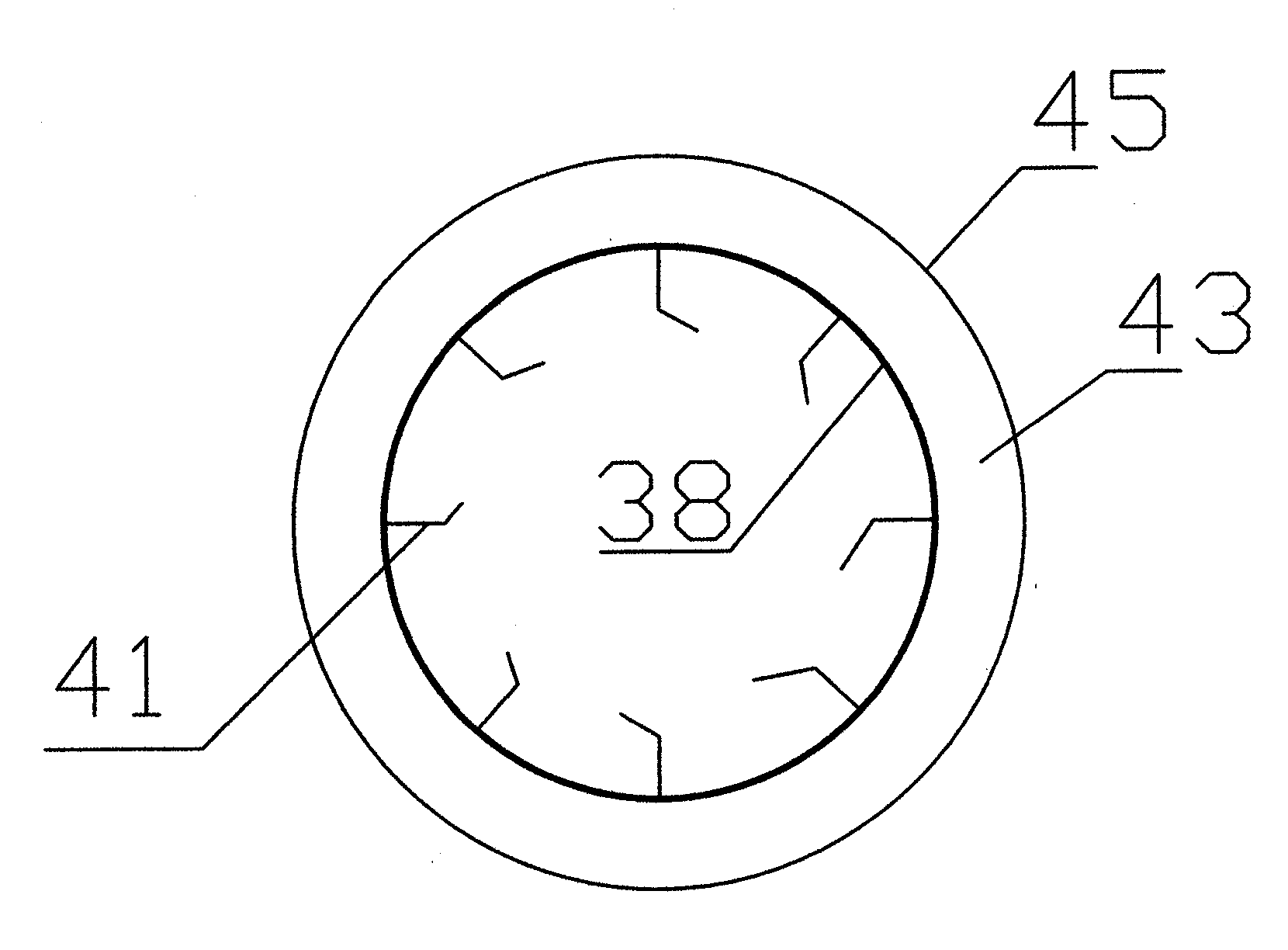
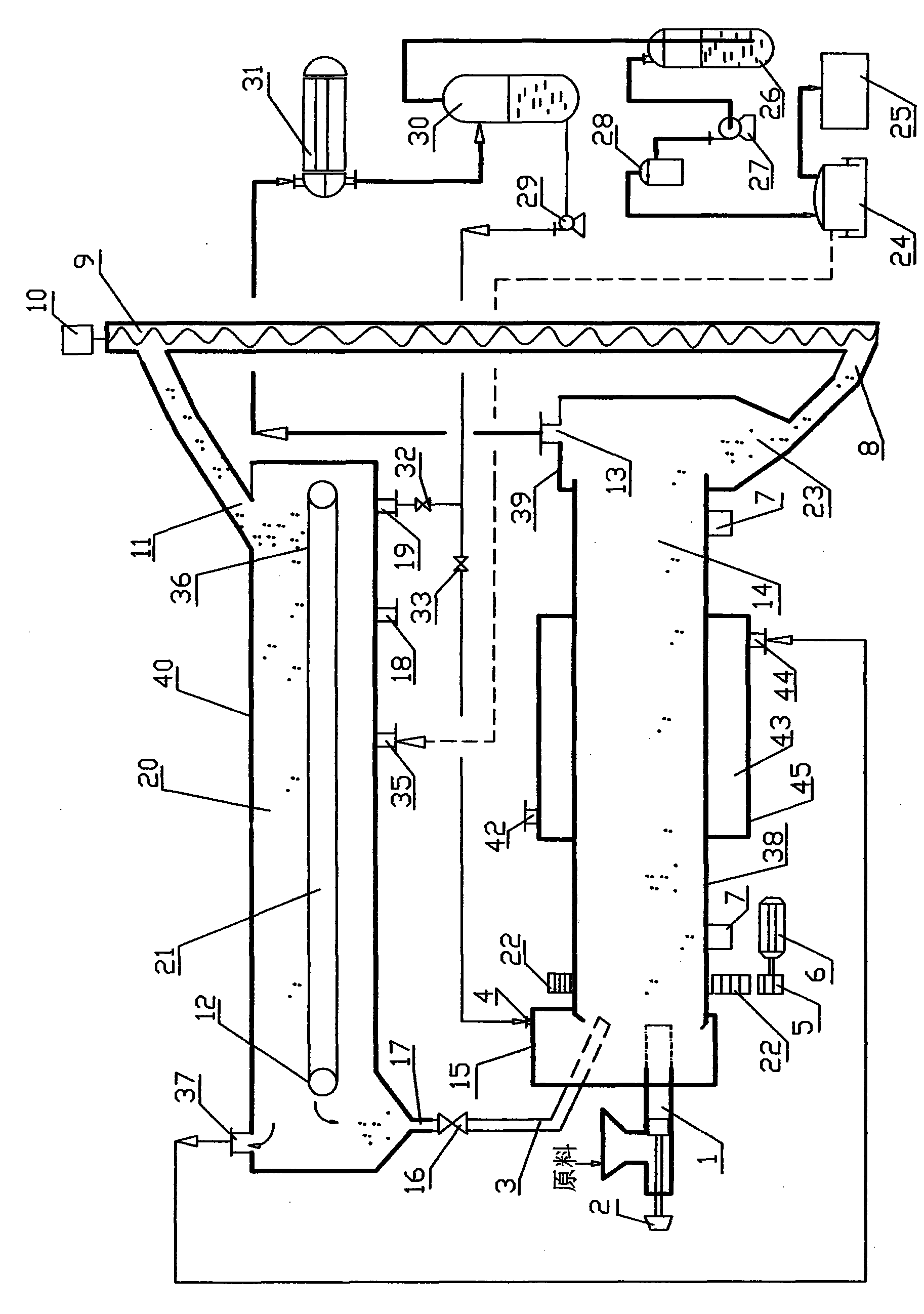
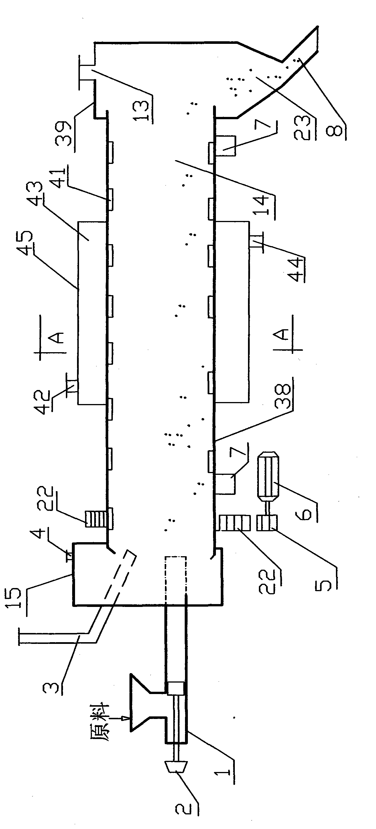
[0036] combined with figure 1 , figure 2 , image 3 and Figure 4 First, heat the granular heat carrier in the incinerator (20) to a high temperature of 700-800°C, then fall into the sealed horizontal rotary pyrolysis reactor (14) through the valve (16), and use the motor ( 6) Drive the gear discs (5, 22) to rotate and drive the horizontal rotary pyrolysis reactor (14) to rotate. At the same time, the motor (2) drives the reciprocating hydraulic feeder (1) to work. The feeder (1) feeds the domestic waste no larger than 30 cm in size after pretreatment and removal of inorganic impurities into the sealed horizontal rotary pyrolysis reactor (14 cm) at a feed rate of 80 kg / min ), and directly mixed with 700-800°C granular heat carrier, use high-temperature granular heat carrier to directly heat the raw material, or / and use high-temperature flue gas to indirectly heat the shell heating chamber of the horizontal rotary pyrolysis reactor Heating, the temperature of the domestic ...


PUM

PropertyMeasurementUnit
sizeaaaaaaaaaa
diameteraaaaaaaaaa

Abstract

The invention discloses a device for production of fuel oil and fuel gas and / or flue gas power generation through household garbage. The device is mainly composed of a horizontal-type rotating pyrolytic reaction kettle, a material feeding machine, an incinerator, a conveying device, a condenser, a gas-liquid separator, a water-sealing pot, a flue gas purifying device, a flue gas fan, a flue gas cabinet, an oil pump and a flue gas generator set. In the device, a high-temperature granular heat carrier and the household garbage are directly contacted to each other in a sealed and oxygen-free horizontal-type rotating pyrolytic reaction kettle for enabling the household garbage to be subjected to a pyrolytic reaction to produce fuel oil or nitrogen-free high-calorific-value fuel gas. The device can achieve continuous production, is free from coking, is high in heat transmission efficiency and is free of generation of dioxin.

Description

technical field [0001] The invention relates to equipment for producing fuel oil, gas or / and gas-fired power generation from domestic garbage, and belongs to the field of environmental protection equipment. Background technique [0002] Relevant domestic garbage or organic matter dry distillation and cracking equipment have been reported, in JP 4-50929 (10) 7-166171 and 3-86790 and Showa 60-58485, 63-132995, 63-178195 and USP4851601 and EP-A-0607862 (The applicant is MAZDA MOTOR CORPORATION) adopts kettle type [vertical or horizontal] reactor for pyrolysis reaction, the outer wall of the kettle is directly heated at high temperature, the material on the inner wall of the kettle is heated intermittently, the temperature difference between the two sides of the kettle wall is large, and the outer wall of the kettle is easily burned out by high temperature Deformation, easy local overheating and coking of the inner wall of the kettle, affecting product conversion rate and equipm...

Claims


Application Information

Patent Timeline
Patent Type & Authority Applications(China)
IPC IPC(8): B09B3/00B09B5/00C10B53/00
CPCY02E50/10
Inventor 周鼎力邢力
Owner 光大环保能源(沛县)有限公司
Why Eureka
Try Eureka