Comb capacitive micro accelerometer

An accelerometer, comb capacitance technology, applied in the direction of measurement of acceleration, speed/acceleration/impact measurement, measurement device, etc., can solve the problems of small detection capacitance area, low measurement accuracy, large detection capacitance area, etc. The effect of increasing, high dimensional control accuracy, and improving measurement accuracy

Inactive Publication Date: 2017-12-12
INST OF ELECTRONICS ENG CHINA ACAD OF ENG PHYSICS
View PDF4 Cites 0 Cited by
  • Summary
  • Abstract
  • Description
  • Claims
  • Application Information

AI Technical Summary

Problems solved by technology

[0003] 1. "Sandwich" structure, the quality block can be made very large in both thickness and area, so the detection capacitor has a large area and low noise, which can meet the requirements of high-precision measurement, but it is generally prepared by wet corrosion processing method, Wet etching control accuracy is poor and additional chip area is required to realize 54.5° inclined groove (54.5° is the angle required to reach the crystal plane). In addition, double-sided alignment photolithography and etching are required, and the process is relatively complicated
[0004] 2. The "comb tooth" structure generally uses dry etching to obtain a fast etching rate and vertical side walls, with high dimensional control accuracy and a small chip structure area. Limits, the thickness of the mass block is small, the area of ​​the detection capacitor is small, the noise is large, and the measurement accuracy is low
If the mass block is increased by increasing the area, and the detection capacitance is increased by increasing the length of the comb teeth, on the one hand, the number of devices on the entire silicon wafer is reduced, and on the other hand, the symmetry of the device is reduced due to the warpage of the silicon wafer. It is difficult to meet the requirements of high-precision measurement
[0005] It can be seen from the above that the micro-accelerometer with sandwich structure can meet the requirements of high-precision measurement, but it needs to improve the dimensional control accuracy and reduce the complexity of the process; the comb-tooth micro-accelerometer has good processability, but it needs to further increase the quality block and detection Capacitance to improve measurement accuracy

Method used


Image

  • Comb capacitive micro accelerometer
  • Comb capacitive micro accelerometer
  • Comb capacitive micro accelerometer

Examples


Embodiment Construction

[0015] The present invention will be described in detail below in conjunction with the accompanying drawings. The description in this part is only exemplary and explanatory, and should not have any limiting effect on the protection scope of the present invention.

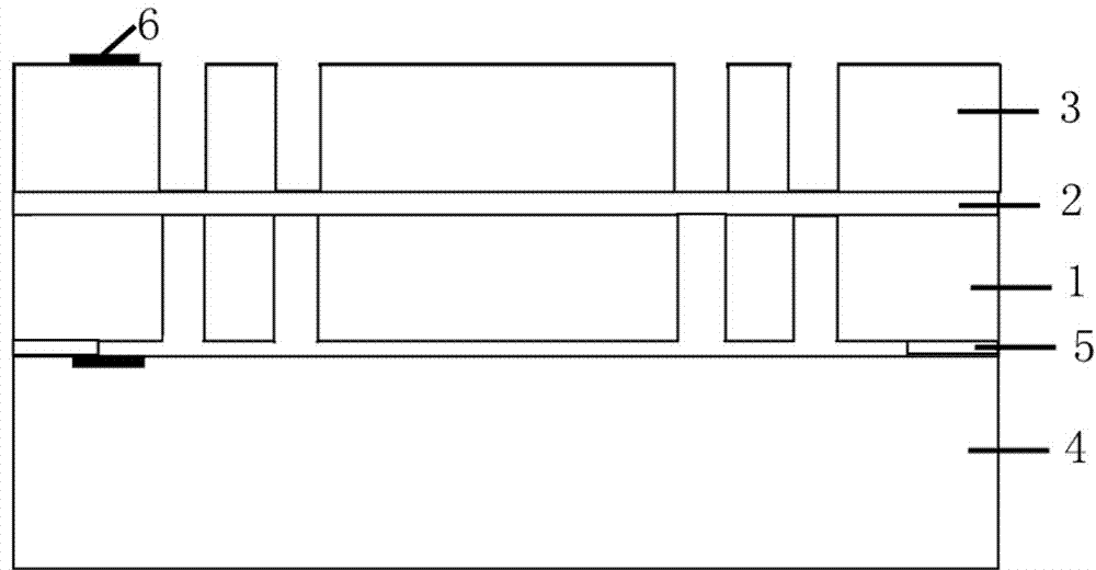
[0016] like figure 1 A comb-tooth capacitive micro-accelerometer shown is composed of a structural layer 1, an insulating layer 2, a substrate layer 3 and a base layer 4, and functional units are arranged on the structural layer 1 and the substrate layer 3, and the structural layer 1 and the substrate layer 4 The anchor point 5 is connected, the structural layer 1 is connected to the substrate layer 3 through the insulating layer 2 , and metal lead electrodes 6 are arranged on the substrate layer 4 and the substrate layer 3 . The material of the insulating layer 2 includes silicon dioxide.

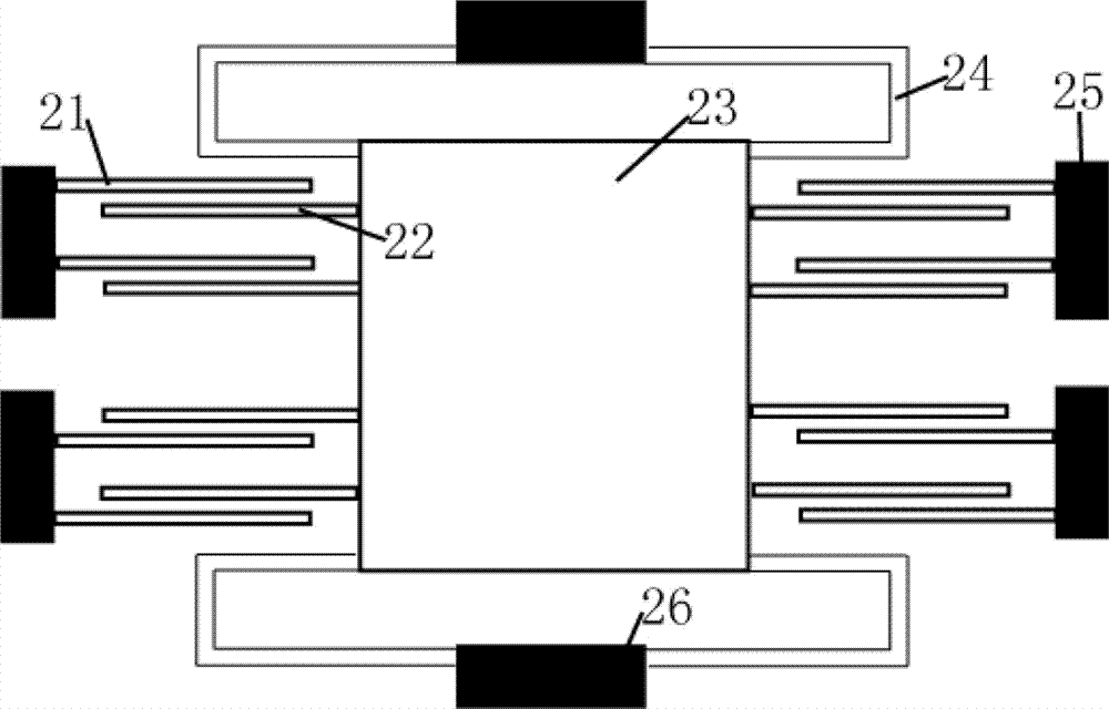
[0017] In order to realize sensing functions such as figure 2 As shown, a fixed electrode 21, a movable electrode 22, a mas...


PUM


Abstract

The invention discloses a comb-tooth capacitive micro-accelerometer, which comprises a substrate layer, an insulating layer, a structural layer and a base layer arranged from top to bottom, the insulating layer is arranged between the substrate layer and the structural layer; Both are equipped with metal lead electrodes. The invention doubles the detection capacitance without increasing the area of ​​the device, increases the weight of the mass block, increases the flexibility of the design, can improve the measurement accuracy, and can use dry etching, with good size control and simple process, and can realize Manufactured in high volumes.

Description

technical field [0001] The invention relates to the technical field of micro-electro-mechanical systems, in particular to a comb-tooth capacitive micro-accelerometer. Background technique [0002] The miniature capacitive accelerometer realized by microelectromechanical system (MEMS) technology has the advantages of small size, light weight, high precision and low cost, and has wide application prospects in military, automotive technology, consumer electronics and other fields . Capacitive micro accelerometers generally have two structures: "sandwich" structure and "comb tooth" structure. [0003] 1. "Sandwich" structure, the quality block can be made very large in both thickness and area, so the detection capacitor has a large area and low noise, which can meet the requirements of high-precision measurement, but it is generally prepared by wet corrosion processing method, Wet etching control accuracy is poor and additional chip area is required to realize 54.5° inclined g...

Claims


Application Information

Patent Timeline
Patent Type & Authority Patents(China)
IPC IPC(8): G01P15/125
Inventor 张照云苏伟唐彬彭勃陈颖慧
Owner INST OF ELECTRONICS ENG CHINA ACAD OF ENG PHYSICS
Why Eureka
Try Eureka