2mum coherent wind lidar polarization state matching and correcting system

A technology of laser radar and coherent wind measurement, which is applied in the direction of radio wave measurement system, measurement device, electromagnetic wave re-radiation, etc., can solve the problems of matching and correction system or equipment, no real-time monitoring of polarization state, etc., to achieve auxiliary matching and guarantee Detection sensitivity and the effect of improving the heterodyne efficiency of the system

Active Publication Date: 2014-11-05
BEIJING RES INST OF SPATIAL MECHANICAL & ELECTRICAL TECH
View PDF2 Cites 9 Cited by
  • Summary
  • Abstract
  • Description
  • Claims
  • Application Information

AI Technical Summary

Problems solved by technology

At present, the existing coherent wind lidar systems do not have real-time monitoring, matching and correction systems or equipment for the polarization state. Therefore, it is urgent to design a method for polarization state monitoring and correction.

Method used


Image

  • 2mum coherent wind lidar polarization state matching and correcting system
  • 2mum coherent wind lidar polarization state matching and correcting system
  • 2mum coherent wind lidar polarization state matching and correcting system

Examples


Embodiment approach 1

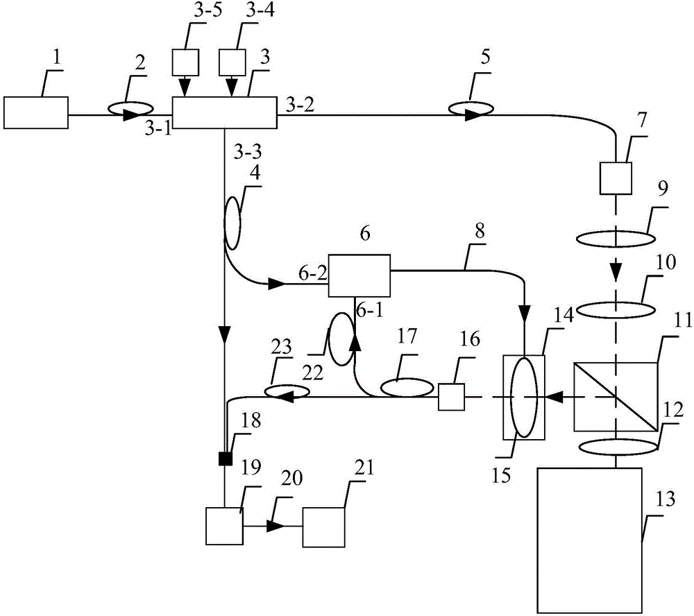
[0036] Embodiment 1: This embodiment is as follows figure 1 As shown, the 2 μm laser 1 emits a laser signal, which is input to the acousto-optic frequency shifter 3 after passing through the first single-mode polarization-maintaining fiber 2 and the input port 3-1 of the acousto-optic frequency shifter 3; adjust the frequency modulation port 3-4 Voltage to 5.2V, RF power modulation port 3-5 voltage to 1.0V, so that the acousto-optic frequency shifter 3 reaches the maximum diffraction efficiency, and two lasers are output from the 0th order diffraction port 3-3 and the 1st order diffraction port 3-2 Signal; the laser beam output by the first-order diffraction port 3-2 is transmitted through the second single-mode polarization-maintaining optical fiber 5, and after being collimated by the pigtailed Green self-focusing lens 7 with an intercept of 0.23, a coherent wind-measuring lidar pulse is formed Signal;

[0037] After the coherent wind laser radar pulse signal is shaped by t...

Embodiment approach 2

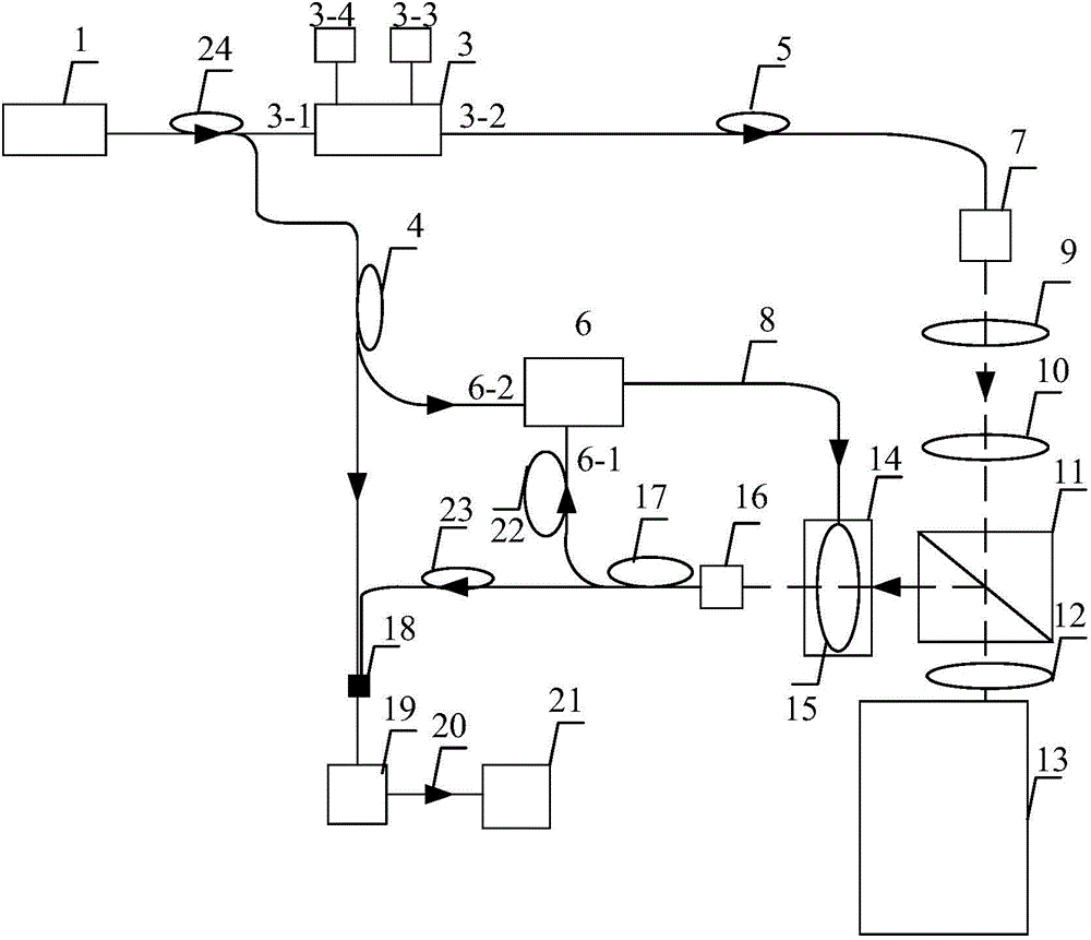
[0043] Implementation mode two: this implementation scheme is as follows figure 2 As shown, the 2 μm laser 1 emits a laser signal, and generates a split laser signal through the third optical fiber beam splitter 24, wherein one of the split signals passes through the input port 3-1 of the acousto-optic frequency shifter 3 and then is input to the acousto-optic frequency shifter 3. Adjust the voltage of the frequency modulation port 3-4 to 5.2V, and the voltage of the RF power modulation port 3-5 to 1.0V, so that the acousto-optic frequency shifter 3 reaches the maximum diffraction efficiency, and outputs one channel from the first-order diffraction port 3-2 Laser signal; the laser beam is transmitted through the second single-mode polarization-maintaining optical fiber 5 and collimated by the pigtailed Green self-focusing lens 7 with an intercept of 0.23 to form a coherent wind laser radar pulse signal;

[0044] After the coherent wind laser radar pulse signal is shaped by th...

Embodiment approach 3

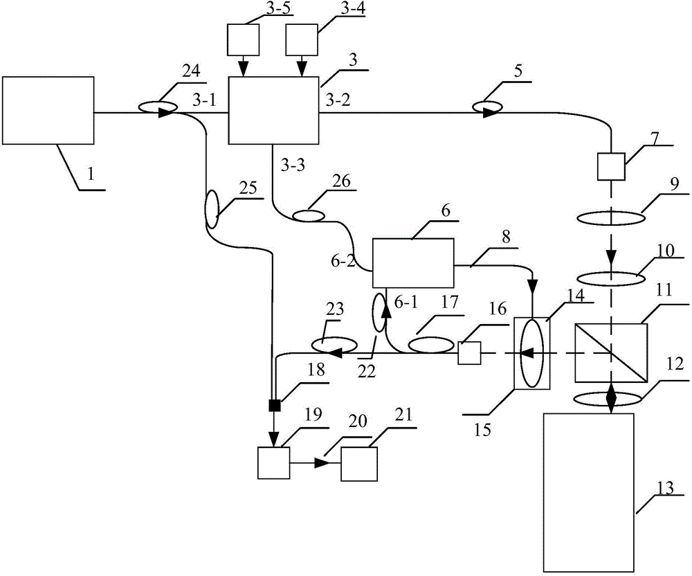
[0050] Implementation Mode Three: This implementation mode is as follows image 3 As shown, the 2 μm laser 1 emits a laser signal, and generates a split laser signal through the third optical fiber beam splitter 24, wherein one of the split signals passes through the input port 3-1 of the acousto-optic frequency shifter 3 and then is input to the acousto-optic frequency shifter 3; Adjust the voltage of the frequency modulation port 3-4 to 5.2V, and the voltage of the RF power modulation port 3-5 to 1.0V, so that the acousto-optic frequency shifter 3 reaches the maximum diffraction efficiency, from the 0th order diffraction port 3-3 and 1 The first-order diffraction port 3-2 outputs two laser signals; the laser beam output by the first-order diffraction port 3-2 is transmitted through the second single-mode polarization-maintaining optical fiber 5, and passes through the pigtailed Green self-focusing lens 7 with an intercept of 0.23. After straightening, a coherent wind lidar p...


PUM


Abstract

The invention relates to a 2mum coherent wind lidar polarization state matching and correcting system, which comprises a 2mum laser, a first single-mode polarization-maintaining fiber, an acoustooptic frequency shifter, a second single-mode polarization-maintaining fiber, a tail fiber-type Grin lens, a lambda/2 wave plate, a lens, a polarization beam splitter prism, a lambda/4 wave plate, an off-axis optical antenna, a stepper motor drive device, a polarizer, a first tail fiber-type coupling lends, a double-channel polarization state analyzer system, a second fiber beam splitter, a photodiode, a coaxial cable, and an oscilloscope. The system can monitor each polarization state situation of reference local oscillation laser signals and laser echo signals in the coherent wind lidar system in real time. when polarization state of two light beams are not matched, the double-channel polarization state analyzer system can automatically correct the polarization state of the laser until matching is realized, thereby greatly improving the heterodyne efficiency of the coherent wind lidar system and improvising detection sensitivity of the system.

Description

technical field [0001] The invention relates to a 2μm coherent wind laser radar polarization state matching and correction system. The system can monitor the polarization state matching between the local oscillator reference laser signal and the echo laser signal in the 2μm coherent wind laser radar system in real time. Coherent wind lidar systems for spaceborne, airborne and ground-based platforms. Background technique [0002] Coherent wind lidar is widely used in the field of weak laser signal detection due to its detection sensitivity close to the quantum noise limit, high signal-to-noise ratio, and high-precision clear-sky detection capability. Wind lidar has been proven to be one of the most effective means to study small and medium-scale meteorological phenomena, and it is of great significance to many aspects such as weather forecasting, military defense, and aviation safety warning. [0003] Coherent wind lidar is based on the Mie scattering of aerosols in the atmo...

Claims


Application Information

Patent Timeline
Patent Type & Authority Applications(China)
IPC IPC(8): G01S7/497G01S17/95
CPCG01S7/497G01S17/95Y02A90/10
Inventor 高龙荣威孙琼阁张宇峰
Owner BEIJING RES INST OF SPATIAL MECHANICAL & ELECTRICAL TECH
Why Eureka
Try Eureka