Self-lubricating bearing plate sintering method and plate containing frame used in method
A self-lubricating bearing and plate frame technology, which is applied in the field of metal sintering, can solve the problems of inability to ensure the thermal distribution of layers and the uniformity of the sintering atmosphere, reduce the performance of sintered products, and unstable sintering quality, so as to improve the production quantity and efficiency. Improve the effect of reasonable structure and size
- Summary
- Abstract
- Description
- Claims
- Application Information
AI Technical Summary
Problems solved by technology
Method used
Image
Examples
Embodiment 1
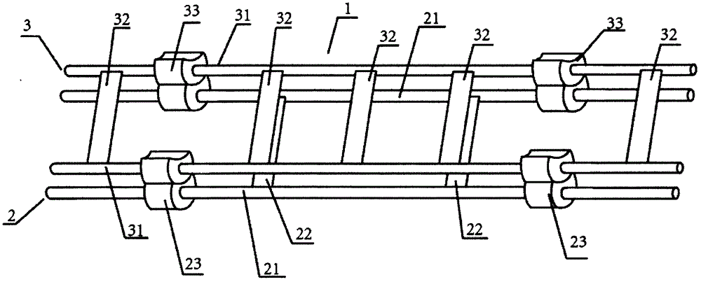
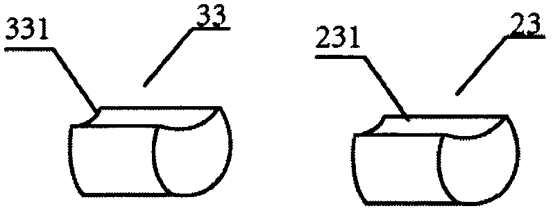
[0039] See attached Figure 1-2 , a self-lubricating bearing plate sintering plate rack 1, including a plate layer 2, a plate layer 3; the plate layer 2 includes two support rods 21 and two connecting rods 22; the two support rods Both ends are covered with fixing parts 23; all fixing parts are in the shape of a cylinder, and the surface is provided with a concave surface 231 with an upward opening;
[0040] Described putting board layer 3 comprises two support rods 31 and five connecting rods 32; The two ends of all support rods are all covered with fixing parts 33; Concave surface 331; all the fixing parts can be correspondingly snapped into the concave surface 231; among the five connecting rods, three connecting rods are located between the fixing parts at both ends of the support rod, and one connecting rod is located at a support near the fixing part and the fixing part Between the end points of the rods, there is a connecting rod between another fixing member and the e...
Embodiment 2
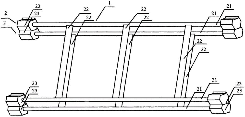
[0043] See attached Figure 3-4 , a self-lubricating bearing plate sintering plate frame 1, including two layers of plate layer 2; the plate layer 2 includes two support rods 21 and three connecting rods 22; both ends of the support rods are covered with Fixing piece 23; All fixing pieces are regular hexahedron shape, and its surface is provided with the concave surface 231 that opening faces up; Among the three connecting rods, one connecting rod is positioned in the middle of the fixing pieces at both ends of the support rod, and one connecting rod is positioned at a fixed There is a connecting rod between the other fixing part and the middle connecting rod between the fixing part and the middle connecting rod;
[0044] The connecting rod is inserted into the support rod; the cross-sectional area of the support rod is 50mm 2 .
Embodiment 3
[0046] See attached Figure 5 , a self-lubricating bearing plate sintering plate frame 1, including two layers of plate layer 2;
[0047] The board layer 2 includes three connecting rods 22 and two supporting rods 21; the two ends of the supporting rods 21 are provided with fixing parts 23; 232; the two ends of a connecting rod in the connecting rod 22 are respectively wound in a single circle on the supporting rod in contact with it to form a winding knot 221 and a winding knot 222; the winding knot 221 and the winding knot 222 are connected with the adjacent layer Among the three connecting rods, one connecting rod is located between the fixing parts at both ends of the supporting rod, one connecting rod is located between a fixing part and the end point of the supporting rod close to the fixing part, and one connecting rod is located at the other end. between a fixing member and the end of the support rod adjacent to the fixing member;
[0048] The cross-sectional area of...
PUM
| Property | Measurement | Unit |
|---|---|---|
| area | aaaaa | aaaaa |
| area | aaaaa | aaaaa |
| area | aaaaa | aaaaa |
Abstract
Description
Claims
Application Information
 - R&D
- Intellectual Property
- Life Sciences
- Materials
- Tech Scout
- Unparalleled Data Quality
- Higher Quality Content
- 60% Fewer Hallucinations
Browse by: Latest US Patents, China's latest patents, Technical Efficacy Thesaurus, Application Domain, Technology Topic, Popular Technical Reports.
© 2025 PatSnap. All rights reserved.Legal|Privacy policy|Modern Slavery Act Transparency Statement|Sitemap|About US| Contact US: help@patsnap.com


