
A method for actively modifying the surface of metal plastic forming dies

A plastic forming and active technology, which is applied in metal processing equipment, manufacturing tools, welding equipment, etc., can solve problems such as poor retestability of the method, limited implementation objects, failure to change the forming performance of the mold, etc., and achieve excellent plastic forming performance and surface layer Effects of refinement of metal grain structure and improvement of wear resistance

Inactive Publication Date: 2016-08-24
JIANGSU UNIV
View PDF10 Cites 0 Cited by
  • Summary
  • Abstract
  • Description
  • Claims
  • Application Information

AI Technical Summary

Problems solved by technology

[0004] Chinese patent 200410010847.4 discloses a laser quenching and hardening treatment method for cutting tools and mold edges. This method only performs surface modification treatment on the workpiece, and does not involve modification treatment on the surface of the workpiece, that is, it fails to change the formability of the mold.
[0007] The published information shows that the existing technology has limitations and particularities in the implementation of surface modification of laser forming molds, which are specifically manifested in: 1. The implementation object is limited to barrel-shaped parts or simple formed parts; 2. Only the convex mold can be determined. Or the rounded corner area of ​​the concave die needs to be surface modified, and the degree of surface modification cannot be judged; 3. It cannot be implemented in some forming molds without punch rounded corners, such as spherical parts; 4. For different formed parts, there is no one A set of standard methods for formulating surface modification schemes, and the reproducibility of the methods is poor

Method used


Image

  • A method for actively modifying the surface of metal plastic forming dies
  • A method for actively modifying the surface of metal plastic forming dies
  • A method for actively modifying the surface of metal plastic forming dies

Examples


Embodiment 1

[0024] The specific implementation of the method of the present invention in Example 1 is as follows.

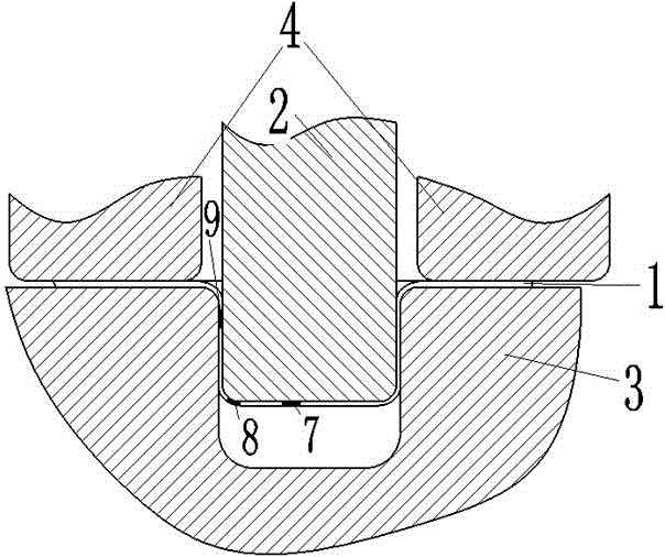
[0025] Such as figure 1 The schematic diagram of the stamping forming section of the barrel is shown. The stamping device includes a sheet material 1, a punch A2, a die A3 and a blank holder 4. The plane sheet 1 becomes a barrel-shaped piece under the action of the punch A2 and the die A3, and the blank holder 4 controls the flow of the material during the forming process to prevent the sheet 1 from wrinkling during stretching and drawing.

[0026] Implementation of the inventive method is divided into three steps.

[0027] Step A), determine the key area on the surface of the punch A2. Define the lower surface of the sheet 1 before plastic forming as the plane M1, and calculate the normal distance S from each point in the contact area between the punch A2 and the sheet 1 to the plane M1 at the end of the plastic forming of the sheet 1, S∈[0, Sn]. The point constituting...

Embodiment 2

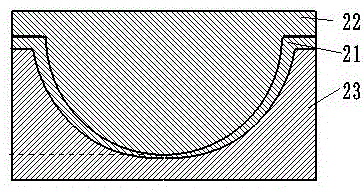
[0039] The formed part of embodiment 2 is a spherical part, and punch B22 and die B23 are corresponding moulds, such as image 3 with Figure 4 .

[0040] Using the same implementation steps as in Example 1, the first-level critical area 27, the second-level critical area 26, and the third-level critical area 25 on the punch B22 are determined, and the areas are distributed in a ring on the punch B22.

Embodiment 3

[0042] The formed part of embodiment 3 is an automobile cover part, and it contains a plurality of forming features, comprises rib 40 and slope 41, such as Figure 5 .

[0043] The difference between embodiment 3 and embodiment 1 or 2 is that the characteristic rib 40 and the slope surface 41 need to be considered respectively to determine the critical area on the punch C32 and the corresponding critical level. Considering the characteristic rib 40 and the slope surface 41 respectively, the surface roughening treatment plan for the punch C32 is obtained. In the case of only considering the characteristic rib 40, it is considered that the formed part is the rib 40, then the forming punch is the rib-shaped protrusion 50 on the punch C32, and the forming die is the rib-shaped groove 60 on the die C33, and the same applies to Embodiment 1 And the punch surface roughening treatment method in embodiment 2. The same applies to the case of considering only the slope surface 41 .


PUM

PropertyMeasurementUnit
heightaaaaaaaaaa
diameteraaaaaaaaaa
depthaaaaaaaaaa

Abstract

The invention provides an active modifying method of the surface of metal plastic forming dies. The method comprises the following steps that roughening processing is conducted on the surfaces of the male dies to actively enhance the roughness of the surfaces of the male dies and the material adhesion performance of the surfaces of the male dies; regular concave cavities and regular grooves are formed in the surfaces of the female dies through machining for storage, even distribution and conveying of lubricating oil. The method has the advantages that the roughness of the surfaces of the male dies and the surfaces of the female dies is controlled, material distribution of formed parts is optimized, the surface strength of the formed parts is improved, the surface residual stress state is improved, the thicknesses of the formed parts are made to be evener, stress concentration is weakened and the quality is greatly improved; the abrasive resistance of the surfaces of the dies is greatly improved and the service life of the dies can be prolonged. Compared with a punching technology where the method is not implemented, the probability that the cracking phenomenon occurs is reduced by 47% and the uniformity of the formed parts is improved by 40%.

Description

technical field [0001] The invention relates to a method for actively modifying the surface of a metal plastic forming die, which belongs to the field of mechanical manufacturing. Background technique [0002] Metal plastic forming process plays an important role in mechanical processing, among which stamping process is the most typical and widely used. The stamping process is a process of applying external force to plates, strips, pipes and profiles by presses and molds to cause plastic deformation or separation to obtain stamped parts of the desired shape. In order to meet the aesthetic requirements, modern automotive panels often have complex three-dimensional dimensions, which impose strict requirements on both stiffness and thickness. The thinner thickness will reduce the manufacturing cost and weight of the whole vehicle, and improve the economy of the vehicle. The above requirements put forward new requirements for the traditional stamping process, and the optimizat...

Claims


Application Information

Patent Timeline
Patent Type & Authority Patents(China)
IPC IPC(8): B23K26/352B23K26/14
CPCB23K26/3568
Inventor 康正阳符永宏符昊王浩华希俊
Owner JIANGSU UNIV
Learn More