Counter-voltage reducing circuit of induction cooker and induction cooker including counter-voltage reducing circuit

A technology of step-down circuit and back-voltage reduction, applied in the field of induction cooker, can solve the problems of affecting the synchronous circuit of induction cooker, easy breakdown of IGBT, short-circuit fryer, etc.

Active Publication Date: 2014-11-26
GREE ELECTRIC APPLIANCES INC
View PDF9 Cites 2 Cited by
  • Summary
  • Abstract
  • Description
  • Claims
  • Application Information

AI Technical Summary

Problems solved by technology

Since the oscillating circuit is connected to the G pole through the IGBT, and the oscillating circuit is fed back to the control amplifier circuit through a high-impedance resistor or a capacitor with a small capacitance (large capacitance will affect the oscillation frequency) and then connected to the G pole after amplification, the self- Inductive high voltage is easily interfered by differential mode signals, which affects the synchronous circuit of the induction cooker, so it is prone to E1 (overvoltage) protection or tripping, or even short circuit bombing
And this back pressure value is high, it is easy to break down the IGBT, the greater the power, the higher the back pressure, which will cause damage to the IGBT and cause the induction cooker to fail to work normally.

Method used


Image

  • Counter-voltage reducing circuit of induction cooker and induction cooker including counter-voltage reducing circuit

Examples


Embodiment Construction

[0017] The present invention will be described in further detail below in conjunction with the accompanying drawings and specific embodiments, but not as a limitation of the present invention.

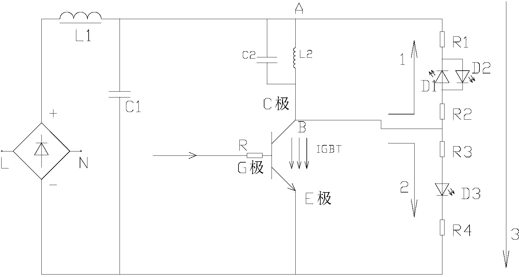
[0018] like figure 1 As shown, according to the embodiment of the present invention, the induction cooker voltage reduction circuit includes a rectification filter circuit, an oscillating circuit and an IGBT circuit connected in sequence, and the electromagnetic furnace voltage reduction circuit also includes a first voltage reduction circuit and a second voltage reduction circuit. The two ends of the step-down circuit are respectively connected to the two ends of the oscillating circuit, the first end of the first step-down circuit intersects with the oscillating circuit at point A, the second end intersects with the oscillating circuit at point B, and then connects to the C pole of the IGBT circuit , the first end of the second step-down circuit is connected to the C pole of the IGBT...


PUM


Abstract

The invention discloses a counter-voltage reducing circuit of an induction cooker and the induction cooker including the counter-voltage reducing circuit. The counter-voltage reducing circuit of the induction cooker includes a rectifying filtering circuit, an oscillation circuit and an IGBT circuit, which are sequentially connected. The counter-voltage reducing circuit of the induction cooker also includes a first step-down circuit and a second step-down circuit. The two ends of the first step-down circuit are connected to the two ends of the oscillation circuit respectively. A first end of the second step-down circuit is connected to a C pole of an IGBT circuit and a second end of the second step-down circuit is connected to an E pole of the IGBT circuit. The counter-voltage reducing circuit of the induction cooker is capable of reducing a counter voltage of the C pole of the IGBT, improving the security of work of the IGBT and effectively preventing explosion of the induction cooker.

Description

technical field [0001] The invention relates to the field of electromagnetic cookers, in particular to an induction cooker reverse voltage reducing circuit and an electromagnetic cooker including the reverse voltage reducing circuit. Background technique [0002] IGBT (Insulated Gate Bipolar Transistor), Insulated Gate Bipolar Transistor, is a composite fully-controlled voltage-driven power semiconductor device composed of BJT (Bipolar Transistor) and MOS (Insulated Gate Field Effect Transistor), with MOSFET The advantages of high input impedance and low conduction voltage drop of GTR (power transistor). The saturation voltage of GTR is low, the carrying current density is large, but the driving current is large; the driving power of MOSFET is small, the switching speed is fast, but the conduction voltage drop is large, and the current carrying density is small. IGBT combines the advantages of the above two devices, with low driving power and low saturation voltage, so it i...

Claims


Application Information

Patent Timeline
Patent Type & Authority Applications(China)
IPC IPC(8): H05B6/06H05B6/12
Inventor 杨钟成冯海杰万今明陈日豪李方烔邹鹏
Owner GREE ELECTRIC APPLIANCES INC
Why Eureka
Try Eureka