Flexible circuit board manufacturing method

A technology of a flexible circuit board and a manufacturing method, which is applied to the formation of electrical connection of printed components and other directions, can solve the problems of complex hole penetration process, large environmental pollution, and substrate hole deviation, achieve good economic and social benefits, reduce The effect of industrial pollution, reducing cost pressure

Active Publication Date: 2014-11-26
上海蓝沛信泰光电科技有限公司
View PDF5 Cites 0 Cited by
  • Summary
  • Abstract
  • Description
  • Claims
  • Application Information

AI Technical Summary

Problems solved by technology
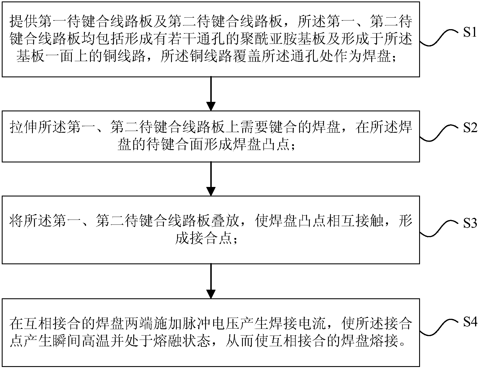
[0008] In view of the above-mentioned shortcomings of the prior art, the purpose of the present invention is to provide a method for manufacturing a flexible circuit board, which is used to solve the problem of complicated hole penetration process and large environmental pollution when making a flexible circuit board in the prior art. Frequent heating of the base material leads to the problem of hole offset

Method used


Image

  • Flexible circuit board manufacturing method
  • Flexible circuit board manufacturing method
  • Flexible circuit board manufacturing method

Examples


Embodiment Construction

[0045]Embodiments of the present invention are described below through specific examples, and those skilled in the art can easily understand other advantages and effects of the present invention from the content disclosed in this specification. The present invention can also be implemented or applied through other different specific implementation modes, and various modifications or changes can be made to the details in this specification based on different viewpoints and applications without departing from the spirit of the present invention.

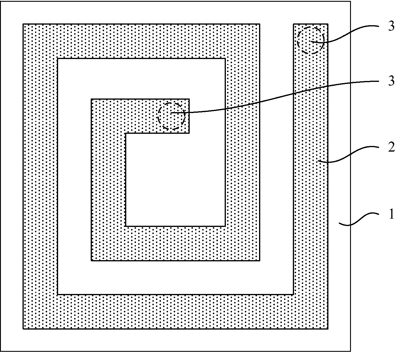
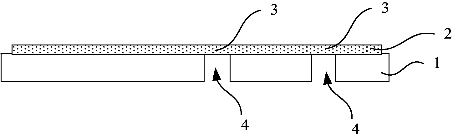
[0046] see Figure 1 to Figure 10 . It should be noted that the diagrams provided in this embodiment are only schematically illustrating the basic idea of ​​the present invention, and only the components related to the present invention are shown in the diagrams rather than the number, shape and shape of the components in actual implementation. Dimensional drawing, the type, quantity and proportion of each component can be changed arb...


PUM


Abstract

The invention provides a flexible circuit board manufacturing method. The flexible circuit board manufacturing method at least comprises the following steps that 1, a first circuit board to be bonded and a second circuit board to be bonded are provided, wherein the first circuit board to be bonded and the second circuit board to be bonded respectively comprise a polyimide substrate and a copper line, each polyimide substrate is provided with a plurality of through holes, each copper line is formed on one face of the corresponding substrate, and the copper lines cover the through holes to serve as bonding pads; 2, the bonding pads, needing to be bonded, on the first circuit board to be bonded and the second circuit board to be bonded are stretched, and bonding pad convex points are formed on the to-be-bonded faces of the bonding pads; 3, the first circuit board to be bonded and the second circuit board to be bonded are stacked, so that the bonding pad convex points make contact to form junction points; 4, pulse voltage is exerted on the two ends of the jointed bonding pads so that welding current can be generated, and the junction points are at a high temperature instantaneously and in a molten state, so that the jointed bonding pads are welded in a fusion mode. The bonding pads are welded in the fusion mode in a pulse voltage spot welding mode, the flexible circuit board holes can be communicated and connected, the process is simple and efficient, and meanwhile good economic benefits and social benefits are obtained.

Description

technical field [0001] The invention belongs to the field of printed circuits and relates to a method for manufacturing a flexible circuit board. Background technique [0002] The key process for the development of flexible circuit boards (Printed Circuit Board, hereinafter referred to as FPC) to multi-layer is "hole penetration". Drilling → chemical method or plasma process to remove dander and residual scum in the "hole" → copper plating (PTH) or black hole → copper plating → pressing photosensitive film → exposure → subsequent processing. [0003] The industry has been discussing for more than ten years: printed circuit board hole metallization technology is one of the keys to printed circuit board manufacturing technology. For a long time, people have been using electroless copper (PTH) method, but the PTH solution contains harmful ecological Various environmental chemical substances such as carcinogenic formaldehyde are complex and costly to treat wastewater; in additi...

Claims


Application Information

Patent Timeline
Patent Type & Authority Applications(China)
IPC IPC(8): H05K3/40
Inventor 王庆军杨兆国戴兴根
Owner 上海蓝沛信泰光电科技有限公司
Why Eureka
Try Eureka