Quick preparation method of die of transparent adhesive tape-carved micro-fluidic chip

A technology of microfluidic chip and scotch tape is applied in the field of rapid preparation of microfluidic chip mold, which can solve the problems of cumbersome process, long processing cycle, inability to modify, etc., and achieve the effect of convenient use and convenient production.

Inactive Publication Date: 2014-12-10
QILU UNIV OF TECH
View PDF4 Cites 10 Cited by
  • Summary
  • Abstract
  • Description
  • Claims
  • Application Information

AI Technical Summary

Problems solved by technology

The above-mentioned molds are mainly prepared by photolithography. Although photolithography can obtain high-quality molds, the preparation of microfluidic chip molds by photolithography requires expensive photolithography machines and ultra-clean room environments. And post-baking and other processes, the process is cumbersome, the cost is high, and the processing cycle is long
In addition, once the microstructure of the mold is determined (such as the width and depth of the microchannels), it cannot be modified

Method used


Image

  • Quick preparation method of die of transparent adhesive tape-carved micro-fluidic chip
  • Quick preparation method of die of transparent adhesive tape-carved micro-fluidic chip
  • Quick preparation method of die of transparent adhesive tape-carved micro-fluidic chip

Examples


Embodiment 1

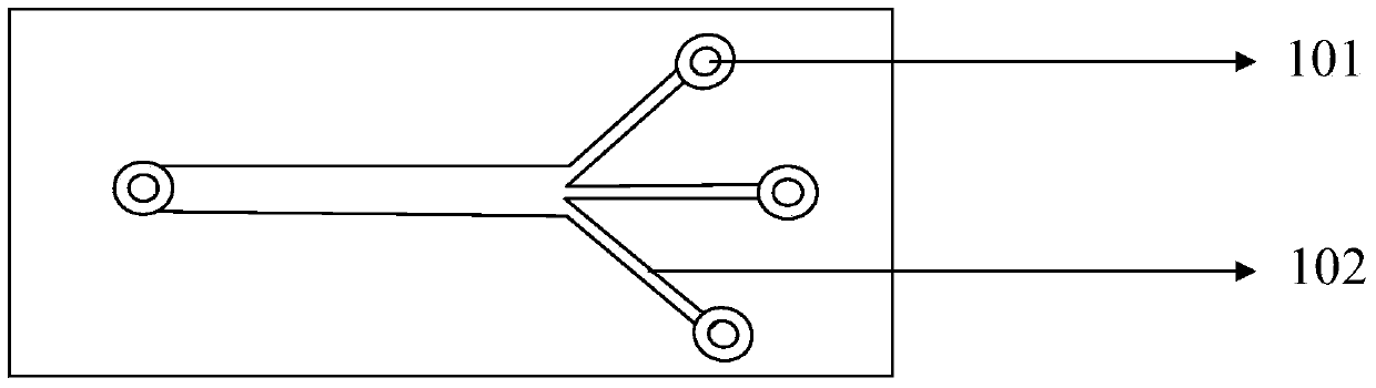
[0059] (1), hand-painted or drawn with computer graphics software such as figure 1 The mold channel pattern shown, the channel width is 1000 μm, the shape is a three-channel bifurcation, and printed;

[0060] (2), clean the surface of the slide glass with a plasma cleaner;

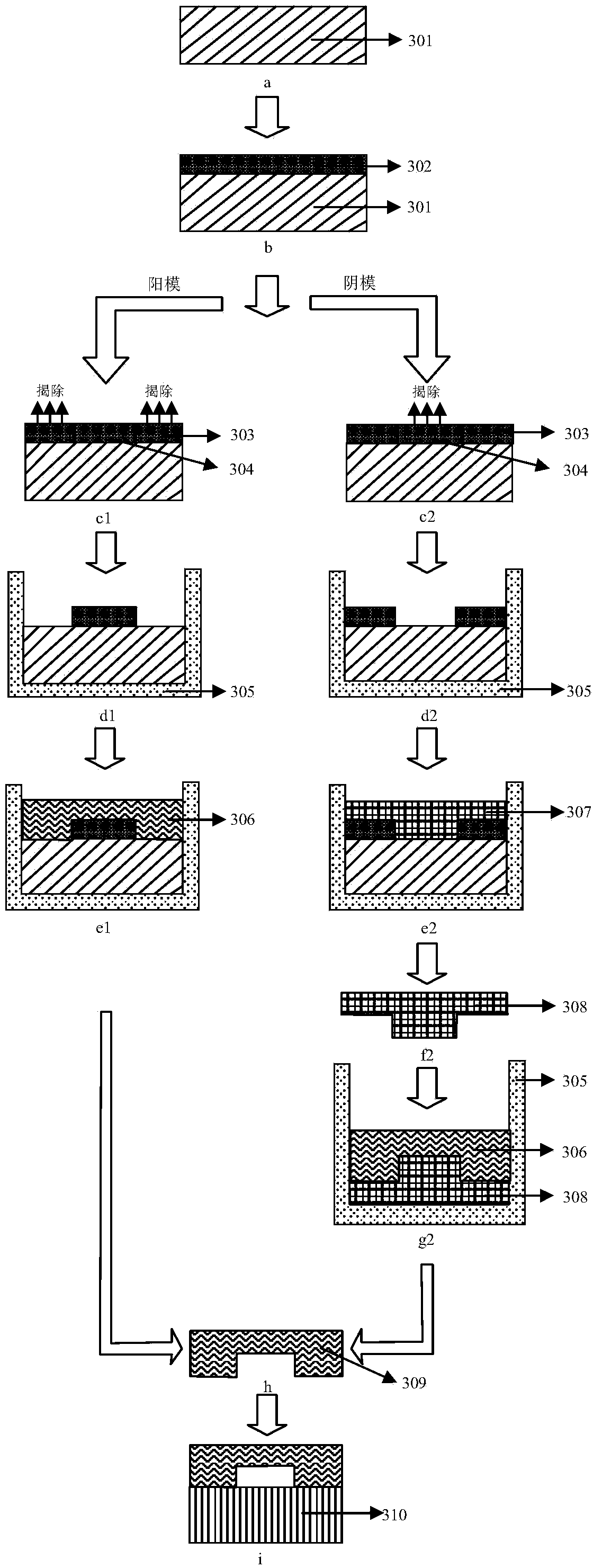
[0061] (3), take a cleaned glass slide (301), and attach two layers of scotch tape (302) with a single layer thickness of 50 μm on it, that is, the required channel depth is 100 μm, such as image 3 -b;

[0062] (4) Place the glass slide with scotch tape on a 70°C electric heating plate for 2 minutes;

[0063] (5) Place the printed mold channel pattern directly under the glass slide that has been attached with scotch tape, and stick it to the lower part of the glass slide so that it cannot be moved;

[0064] (6), use a scalpel to engrave the shape of the channel on the scotch tape along the drawn pattern, such as image 3 -c1;

[0065] (7), the scotch tape (303) around the channel is removed to obtain...

Embodiment 2

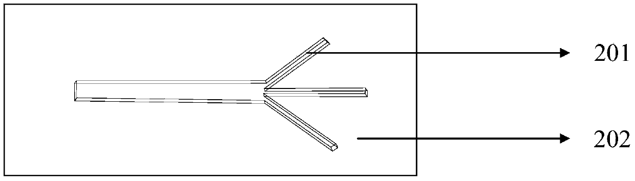
[0070] (1), with example 1 step (1), channel width is 50 μ m, and shape is " cross " shape;

[0071] (2), with example 1 step (2);

[0072] (3), with the example 1 step (3), attach one layer of scotch tape on it, that is, the required channel depth is 50 μm, such as figure 2 shown;

[0073] (4), with example 1 step (4);

[0074] (5), with example 1 step (5);

[0075] (6), with example 1 step (6);

[0076] (7), the scotch tape of channel shape is removed (304), then obtain negative mold, as image 3 -d2 shown;

[0077] (8), with example 1 step (8);

[0078] (9), vacuumize the epoxy resin (307) and pour it into the casting mold, place it on a 65°C electric heating plate for 2 hours to solidify;

[0079] (10), tinfoil paper and cured epoxy resin mold (308) tool are peeled off, can obtain required mold that can be used repeatedly, as image 3 -f2 shown;

[0080] (11), with example 1 step (8);

[0081] (12), with example 1 step (9), as image 3 -g2 shown;

[0082] (13)...


PUM

PropertyMeasurementUnit
widthaaaaaaaaaa

Abstract

The invention aims at providing a quick preparation method of a die formed by carving a transparent adhesive tape by a micron-scale depth and used for manufacturing a PDMS micro-fluidic chip. The transparent adhesive tape is caved by use of a scalpel to form a female die and a male die, and the female die and the male die are further used for manufacturing the micro-fluidic chip die; the channel depth of a micro-fluidic chip can be controlled by changing the number of types and the number of layers of the pasted transparent adhesive tapes; the channel depth and the channel width of the die both can be in the range of 20 microns to 10000 microns; besides, the channel shape, the channel width and the channel depth all can be changed in design according to requirements. The male die formed by carving the transparent adhesive tape can be directly applied to forming the desired PDMS finished products by casting; while the female die formed by use of the transparent adhesive tape needs to be cast by use of an epoxy resin firstly, and after the epoxy resin is cured and dried, an epoxy resin female die which can be repeatedly used for a plurality of times is obtained. The quick preparation method of the die of the transparent adhesive tape-carved micro-fluidic chip is simple to operate and low in cost, is expected to be popularized in general laboratories and is capable of promoting the manufacture and design of the micro-fluidic chips.

Description

Technical field: [0001] The invention relates to a rapid preparation method of a mold for a microfluidic chip, which is a method for making a mold for engraving a micron-level deep channel on a scotch tape. technical background: [0002] Microfluidic technology is a technology developed in recent years to control fluid flow at the microscale. Because of its convenient use and low price, it has been widely used in the fields of biological analysis, cell and microbial culture, and drug synthesis and screening. It is the basis for the next generation of pathogen detection, biological research, and drug synthesis and screening platforms. [0003] Microfluidic chip processing methods are mainly divided into direct processing method and mold replication method. The direct processing method mainly uses laser ablation, computer numerical control (CNC) engraving or etching to directly process microfluidic channels on the chip material. and other structures; while the mold replicatio...

Claims


Application Information

Patent Timeline
Patent Type & Authority Applications(China)
IPC IPC(8): B29C33/38
Inventor 张昊刘彧高健
Owner QILU UNIV OF TECH
Why Eureka
Try Eureka