Solar cell and preparation method thereof

A solar cell and silver electrode technology, applied in circuits, photovoltaic power generation, electrical components, etc., can solve the problems affecting the photoelectric conversion efficiency of solar cells and the decline of silver electrode conductivity, achieve a constant deposition rate, improve conductivity, and ensure conductivity sexual effect

Inactive Publication Date: 2014-12-10
GUANGDONG AIKO SOLAR ENERGY TECH CO LTD
View PDF1 Cites 2 Cited by
  • Summary
  • Abstract
  • Description
  • Claims
  • Application Information

AI Technical Summary

Problems solved by technology

These voids lead to a decrease in the conductivity of the silver electrode...

Method used


Image

  • Solar cell and preparation method thereof
  • Solar cell and preparation method thereof
  • Solar cell and preparation method thereof

Examples


Embodiment Construction

[0035] In order to make the objectives, technical solutions and advantages of the present invention clearer, the present invention will be further described in detail below with reference to the accompanying drawings.

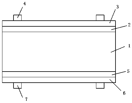
[0036] See figure 1 , figure 1 An existing solar cell is shown. The solar cell includes P-type silicon 1, and an N-type emitter 2 is formed on the front side of the P-type silicon 1 by diffusion, and the front side of the N-type emitter 2 is provided with a passivation film 3. The front surface of the passivation film 3 is provided with a positive electrode 4, the positive electrode 4 is a silver electrode, the back of the P-type silicon 1 is provided with a back passivation layer 5, and the back passivation layer 5 is provided with a back Electric field 6 and back electrode 7.

[0037] Wherein, the positive electrode 4 is a silver electrode.

[0038] In the existing solar cell, after the positive electrode is printed, the silicon wafer is dried and sintered in a sin...


PUM

PropertyMeasurementUnit
Current densityaaaaaaaaaa
Thicknessaaaaaaaaaa

Abstract

The invention discloses a solar cell. The solar cell comprises P type silicon, an N type emitter is formed on the front surface of the P type silicon through diffusion, the front surface of the N type emitter is provided with a passivation film, the front surface of the passivation film is provided with a positive electrode which is a silver electrode, the back surface of the P type silicon is provided with a back passivation layer, the back passivation layer is provided with a back electric field and a back electrode, the silver electrode is electroplated with at least one silver layer, and the silver layer covers the silver electrode. Accordingly, the invention also provides a method of preparing the solar cell. The solar cell is simple in structure, the silver layer can fill voids in the surface of the silver electrode, so that the void ratio of the silver electrode of a traditional solar cell is effectively reduced, the conductivity of the silver electrode is improved, and further the photoelectric conversion efficiency of the cell is enhanced.

Description

Technical field [0001] The invention relates to the technical field of batteries, in particular to a solar battery and a preparation method thereof. Background technique [0002] A solar cell is a device that effectively absorbs solar radiation energy and uses the photovoltaic effect to convert light energy into electrical energy. When the sun shines on the semiconductor PN junction (PN Junction), a new hole-electron pair (VE pair) is formed. ), under the action of the electric field of the PN junction, holes flow from the N area to the P area, and electrons flow from the P area to the N area, and a current is formed after the circuit is turned on. [0003] The manufacturing process of crystalline silicon solar cells has 6 processes, namely texturing, diffusion, dephosphorization silicon glass and back junction, coating, screen printing, and sintering. The screen printing process is divided into three steps: back silver printing, back aluminum printing and positive silver printing...

Claims


Application Information

Patent Timeline
IPC IPC(8): H01L31/0224H01L31/04H01L31/18
CPCH01L31/022425Y02E10/50Y02P70/50
Inventor 方结彬秦崇德石强黄玉平何达能陈刚
Owner GUANGDONG AIKO SOLAR ENERGY TECH CO LTD
Why Eureka
Try Eureka