
Method and device for measuring optical power parameters on basis of crystal resonator

A crystal resonator and parameter measurement technology, which is applied in the direction of photometry using electrical radiation detectors, can solve the problems of weak displacement signal, limited application, large measurement uncertainty, etc., to improve the efficiency and cost ratio, and has strong applicability , compact structure

Inactive Publication Date: 2014-12-17
NORTHWEST INST OF NUCLEAR TECH +1
View PDF7 Cites 13 Cited by
  • Summary
  • Abstract
  • Description
  • Claims
  • Application Information

AI Technical Summary

Problems solved by technology

The problem with this method is that for high-energy and high-power lasers, a large multiple of light intensity attenuation is required, so the attenuation coefficient of the attenuator needs to be accurately calibrated, resulting in a large measurement uncertainty
This method has a weak displacement signal caused by light pressure in the application, so it puts forward higher requirements on the accuracy and resolution of the displacement sensor, which limits the application of this method

Method used


Image

  • Method and device for measuring optical power parameters on basis of crystal resonator
  • Method and device for measuring optical power parameters on basis of crystal resonator
  • Method and device for measuring optical power parameters on basis of crystal resonator

Examples


Embodiment Construction

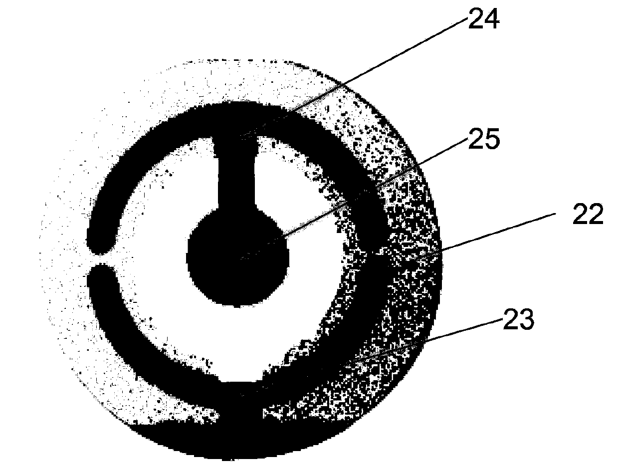
[0034] Taking a common quartz crystal resonator as an example, the measurement principle of the present invention will be introduced below.

[0035] Quartz crystal resonators are referred to as crystal oscillators. They are composed of quartz wafers and electrodes plated on the front and back of the wafers. The electrodes are made of gold, silver, copper and other materials. Usually, their diameter-thickness ratio is greater than 40, which can greatly suppress the non-ground state mode. The coupling improves the working stability of the system. For example, the diameter of a common crystal oscillator is 25.4mm, and the thickness is only 0.3mm.

[0036] When a compressive force or tensile force is applied to the wafer, due to the piezoelectric effect, the crystal will deform and polarize to generate equal amounts of positive and negative charges on the electrodes; if the crystal is connected to a stable self-excited oscillation circuit, it will form a Frequency selection compon...


PUM


Abstract

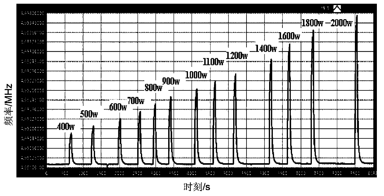
The invention discloses a method and a device for measuring optical power parameters on the basis of a crystal resonator. The device comprises the crystal resonator, an oscillation starting circuit and a frequency measuring unit. An input end of the oscillation starting circuit is connected with an electrode of the crystal resonator, an output end of the oscillation starting circuit is electrically connected with the frequency measuring unit, and to-be-measured light beams are incident on a working surface of the crystal resonator. The method and the device for measuring the optical power parameters have the advantages that incident laser light is effectively reflected during application of the method and the device, the requirement on the laser irradiation bearing ability of a measuring system can be lowered, the method and the device can be used for measuring the high-energy laser parameters under long-time emergent conditions, power of the laser light can be converted into frequencies to be measured during implementation, the method and the device are high in measurement precision and resolution by the aid of a modern frequency measuring technology, requirements on measuring parameters of laser light under different power conditions can be met, the method and the device are high in applicability, wide in dynamic range and simple in engineering, the device is compact in structure, and the like.

Description

technical field [0001] The invention relates to a method and device for measuring optical power parameters, in particular to a method and device for measuring high-energy laser power parameters based on a crystal resonator. Background technique [0002] High-energy lasers refer to lasers with an average power greater than 10,000 watts, a duration of more than several seconds, and an output energy of more than tens of thousands of joules. They have important industrial and military application prospects. At present, the measurement method of high-energy laser power is mainly the photoelectric detection method. The laser is incident on the attenuation unit such as the integrating sphere and the optical attenuation film, and then the laser is incident on the surface of the photodetector after the light intensity is attenuated by a large multiple. By measuring the output signal and the attenuation coefficient value, we can get The power value of the laser. The problem with this...

Claims


Application Information

Patent Timeline
Patent Type & Authority Applications(China)
IPC IPC(8): G01J1/42
Inventor 陈绍武丁彬刘福华斯阳杨鹏翎黄伟吴勇王平冯刚陶蒙蒙
Owner NORTHWEST INST OF NUCLEAR TECH
Learn More