Ultralow-temperature ultra-clean flue gas exhausting system and method for thermal power plant

A discharge system and thermal power plant technology, applied in the direction of separation methods, chemical instruments and methods, and the use of liquid separation agents, can solve the problems of secondary pollution from gypsum rain, white smoke from chimneys, etc., to alleviate white smoke and reduce energy Effect of waste and reduction of water consumption

Inactive Publication Date: 2014-12-24
HUANENG CLEAN ENERGY RES INST
View PDF7 Cites 7 Cited by
  • Summary
  • Abstract
  • Description
  • Claims
  • Application Information

AI Technical Summary

Problems solved by technology

After the flue gas is discharged into the atmosphere, since the atmospheric temperature is much lower than the flue gas temperature (especially in winter in the northern region), the water vapor in the flue gas cools down sharply, and exists in the flue gas as very fine particles of water droplets, generating a large amount of The phenomenon of white smoke from the chimney is very serious, and it will also cause secondary pollution from gypsum rain

Method used


Image

  • Ultralow-temperature ultra-clean flue gas exhausting system and method for thermal power plant
  • Ultralow-temperature ultra-clean flue gas exhausting system and method for thermal power plant
  • Ultralow-temperature ultra-clean flue gas exhausting system and method for thermal power plant

Examples


Embodiment 1

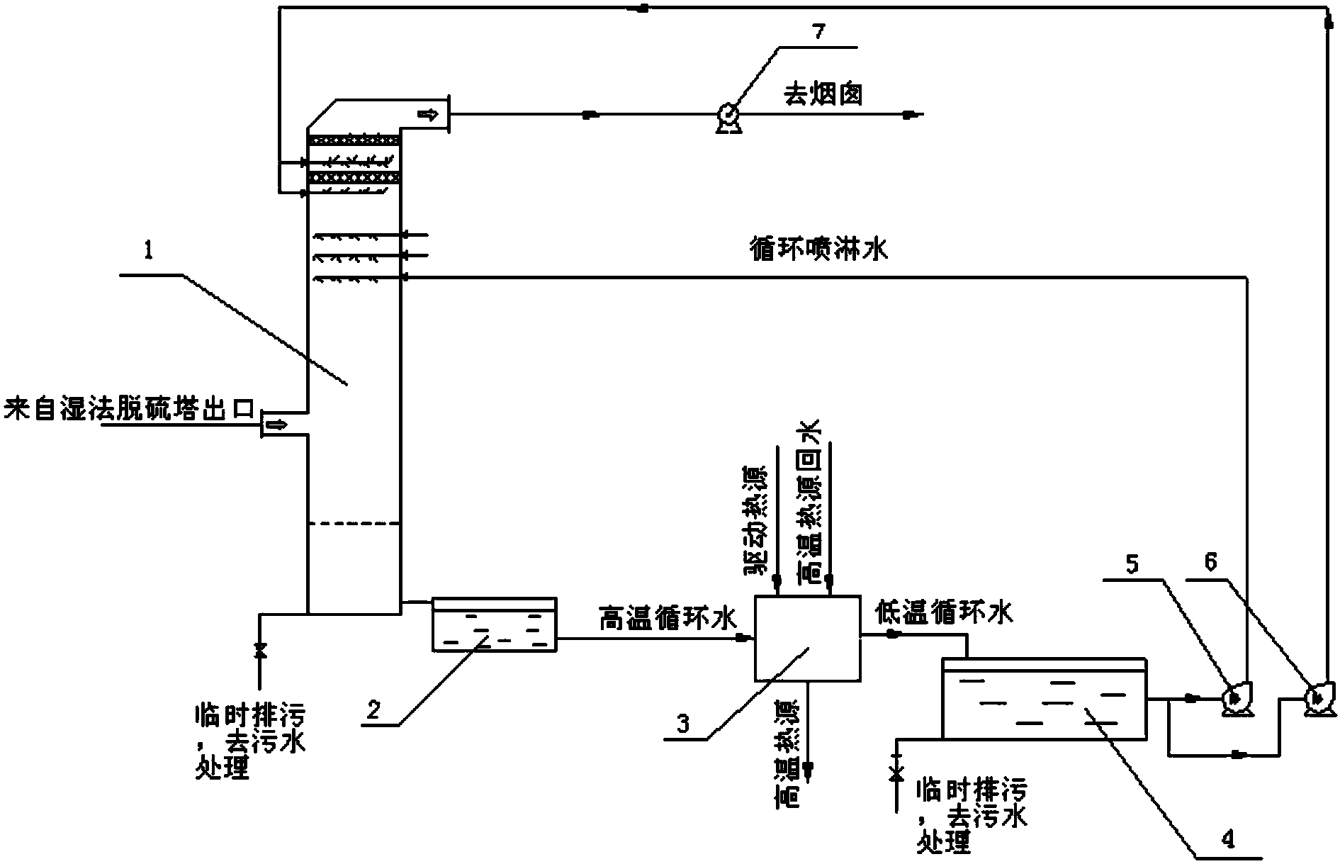
[0032] Such as figure 2As shown, the heat exchange system 3 of this embodiment is an absorption heat pump. The driving heat source of the absorption heat pump comes from the low-pressure cylinder extraction of the steam turbine of the thermal power plant, and the return water of the heat network is used as the working medium of the high-temperature heat source of the absorption heat pump. The discharge method is as follows: the wet flue gas from the outlet of the wet desulfurization tower of the thermal power plant enters through the flue gas inlet of the heat exchange scrubber 1, walks from bottom to top in the heat exchange scrubber 1, and the circulating cooling water is atomized through multi-layer nozzles After walking from top to bottom, the flue gas and the atomized circulating cooling water contact countercurrently in the heat exchange scrubber 1, and a strong heat and mass transfer process occurs, the flue gas is cooled by the circulating cooling water, and the water ...

Embodiment 2

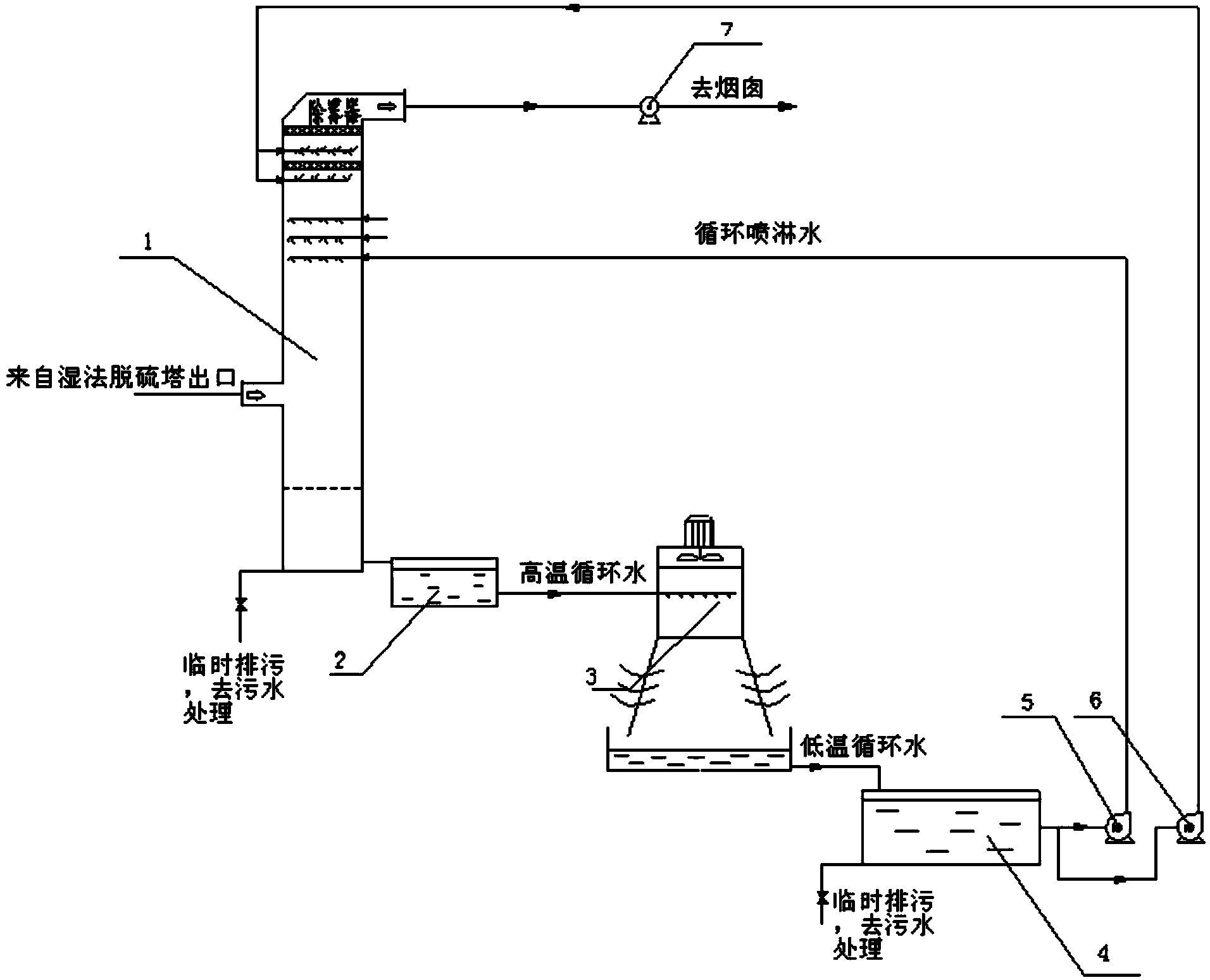
[0034] Such as image 3 As shown, the heat exchange system 3 of this embodiment is a cooling tower. The discharge method is as follows: the wet flue gas from the outlet of the wet desulfurization tower of the thermal power plant enters through the flue gas inlet of the heat exchange scrubber 1, walks from bottom to top in the heat exchange scrubber 1, and the circulating cooling water is atomized through multi-layer nozzles After walking from top to bottom, the flue gas and the atomized circulating cooling water contact countercurrently in the heat exchange scrubber 1, and a strong heat and mass transfer process occurs, the flue gas is cooled by the circulating cooling water, and the water vapor in the flue gas condenses Afterwards, a large amount of condensed water enters the circulating cooling water, the sensible heat of the flue gas and the latent heat of vaporization of the water vapor are absorbed by the circulating cooling water, and the cooled flue gas continues upward...


PUM


Abstract

The invention relates to an ultralow-temperature ultra-clean flue gas exhausting system and method for a thermal power plant. Flue gas from a wet desulphurization outlet enters from the lower part of a heat exchange scrubbing tower and flows from bottom to top, circulating cooling water flows from top to bottom in the heat exchange scrubbing tower after being atomized by a multi-layer nozzle by a circulating water pump, the flue gas and the atomized circulating cooling water are subjected to strong heat and mass transfer, a great amount of moisture is separated out in the reduction process of flue gas temperature, and a great amount of heat is released; and besides, pollutants in the flue gas are captured by the circulating cooling water, the circulating cooling water is drained through the lower part of the heat exchange scrubbing tower after absorbing the moisture and the heat in the flue gas, enters a circulating water treatment system to be subjected to sedimentation, filtering and chemicals treatment, then enters a heat exchange system to be cooled and is recycled. The system is simple and convenient to operate, can effectively alleviate the phenomenon that a chimney exhausts white smoke after wet desulphurization, can achieve the ultra-clean emission of flue gas of the thermal power plant, can recycle moisture and low-grade heat in the flue gas and has the good environment protection property and the high economical efficiency.

Description

technical field [0001] The invention relates to the technical field of flue gas emission in thermal power plants, in particular to a system and method for ultra-low temperature and ultra-clean emission of flue gas in thermal power plants. Background technique [0002] With the increasingly stringent national environmental protection requirements, the environmental protection indicators of thermal power generating units are required to develop towards ultra-clean emission standards. At present, conventional coal-fired power generation units mainly use SCR / SNCR+FGD+bag filter+low-nitrogen combustion technology to control pollutants. The above-mentioned pollutant control technology can realize the pollutant emission of coal-fired power generation units to meet the latest environmental protection emission requirements, but Still can not meet the requirements of ultra-clean emission, using ultra-low temperature ultra-clean emission technology of flue gas, the flue gas at the outl...

Claims


Application Information

Patent Timeline
Patent Type & Authority Applications(China)
IPC IPC(8): B01D53/18B01D53/14B01D47/06
Inventor 肖平李强徐正泉江建忠
Owner HUANENG CLEAN ENERGY RES INST
Why Eureka
Try Eureka