Pipeline Interface Wave Ultrasonic Tracking System and Method

A tracking system and interface wave technology, applied in the pipeline system, using sound waves/ultrasonic waves/infrasonic waves to analyze solids, mechanical equipment, etc., can solve problems such as increased errors, decreased detection speed, and decreased data volume, so as to achieve accurate measurement and improve The effect of detecting speed and increasing repetition rate

Active Publication Date: 2017-03-08
NANTONG UNION DIGITAL TECH DEV
View PDF4 Cites 0 Cited by
  • Summary
  • Abstract
  • Description
  • Claims
  • Application Information

AI Technical Summary

Problems solved by technology

The thickness of the water intake layer is 100mm, the thickness of the workpiece is 10mm, the sound velocity in water is 1480mm / ms, and the sound velocity in the workpiece is 5900mm / ms. At this time, the required sampling time is at least: 2×(100 / 1480+(10×4) / 5900)=0.1487 ms=14870×10ns, for 100MHz, 8bit word length analog-to-digital converter, the sampling data is 1B every 10ns, then the data volume of each sampling is 14870B, and the data volume per second is: 14870B×2KB is approximately equal to 29MB, so large The amount of data cannot be processed effectively and timely by the data transmission system, data storage system and data calculation and analysis system
In order to reduce the amount of data, the only way to reduce the repetition frequency is to reduce the detection speed; to reduce the sampling depth, but to reduce the effective data; to perform data compression, but to increase the hardware burden and increase the error
In fact, the data in the water layer is invalid for detection, so if you do not sample the data in the water, but sample the data in the workpiece, the data is only 2KB×2×((10×4) / 5900)×1000× 100=2.7MB, the amount of data has dropped by an order of magnitude

Method used


Image

  • Pipeline Interface Wave Ultrasonic Tracking System and Method
  • Pipeline Interface Wave Ultrasonic Tracking System and Method

Examples


Embodiment Construction

[0023] The present invention will be further described below in conjunction with the accompanying drawings.

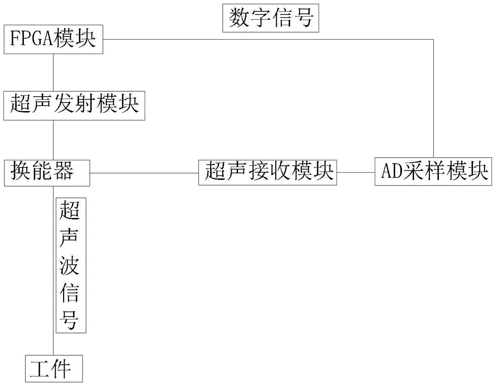
[0024] The purpose of the invention is to track the interface wave, extract the ultrasonic data from the interface wave to the echo of the outer wall of the workpiece, and reduce the effective data volume of the detection system. The realization of the present invention is based on the ultrasonic detection system of the FPGA module, the transmission and reception of the transducer are controlled by the FPGA module, and the received data AD sampling is converted into a digital signal at the same time, and the interface wave is detected according to the position of the gate. Data extraction of outer wall echoes.

[0025] Such as figure 1 As shown, the main hardware device connections are as follows:

[0026] The ultrasonic transmitting module is connected with the transducer, the transducer is connected with the ultrasonic receiving module, and the ultrasonic receiving...


PUM


Abstract

The invention aims at providing a system and a method for tracking interface waves which are echoes generated between water and workpieces and also called as water layer waves. The system comprises an FPGA module, an ultrasonic transmission module, an ultrasonic reception module, an AD sampling module, a gate position control assembly and a gate width control assembly, wherein the ultrasonic transmission module is used for generating high voltage and transmitting a high-voltage signal to a transducer; the ultrasonic reception module is used for receiving an ultrasonic signal converted electric signal in the transducer; the AD sampling module is used for sampling the received electric signal into a digital signal and sending the digital signal to the FPGA module; the gate position control assembly is used for determining the effective starting position of the sampling; the gate width control assembly is used for determining the range of the effective starting position of the sampling. The system and the method for tracking interface waves are specifically capable of realizing the following functions: (1) exciting an ultrasonic probe and sampling the echoes; (2) tracking the interface waves; (3) simplifying the original ultrasonic data and retaining the data effective to the workpiece detection.

Description

technical field [0001] The invention belongs to the technical field of nondestructive testing, and in particular relates to a method for tracking interface waves when using a liquid immersion method to perform ultrasonic testing on pipelines. Background technique [0002] Pipelines are used to store or transport oil, natural gas, etc., and are usually installed underground or overhead. There are wrapping layers on the outside. The wrapping layer materials are cement, mud, moisturizing materials, etc., so it cannot be detected from the outside, and an internal crawler is required to drive the detection. The equipment is used for flaw detection in the pipeline. [0003] Ultrasonic testing is the most effective non-destructive testing method for pipelines, but ultrasonic testing requires adding a coupling agent between the probe and the workpiece. For pipeline testing channels, automatic ultrasonic testing equipment is used, and water is used as the coupling agent. Ultrasound ...

Claims


Application Information

Patent Timeline
Patent Type & Authority Patents(China)
IPC IPC(8): G01N29/04F17D5/06
Inventor 宋伟卢丽芳王虎
Owner NANTONG UNION DIGITAL TECH DEV
Why Eureka
Try Eureka