Air suction warming method and warming system of gas turbine compressor

A technology for gas turbines and compressors, which is applied to gas turbine devices, air inlets of turbines/propulsion devices, combustion air/combustion-air treatment, etc., and can solve the problem of reducing the work of high-temperature turbines of gas turbines, reducing the efficiency of gas turbines, and consuming electric energy or natural gas and other issues to achieve the effect of reducing adverse effects, increasing temperature, and reducing relative humidity

Inactive Publication Date: 2015-01-28
DONGFANG TURBINE CO LTD
View PDF8 Cites 7 Cited by
  • Summary
  • Abstract
  • Description
  • Claims
  • Application Information

AI Technical Summary

Problems solved by technology

[0005] The above-mentioned additional air intake heating system (electric heating or natural gas heating) needs to be equipped with electric heating equipment or natural gas combustion heating equipment, and needs to consume electric energy or natural gas, and the economy is poor
[0006] The above-mentioned method of using the original compressor extraction as a heat source increases the power consumption of the compressor, reduces the working medium flow rate of the gas turbine burner and high-temperature turbine, and reduces the work of the high-temperature turbine of the gas turbine, which also reduces the energy consumption of the gas turbine. output, but also reduces the efficiency of the gas turbine

Method used


Image

  • Air suction warming method and warming system of gas turbine compressor
  • Air suction warming method and warming system of gas turbine compressor
  • Air suction warming method and warming system of gas turbine compressor

Examples


Embodiment 1

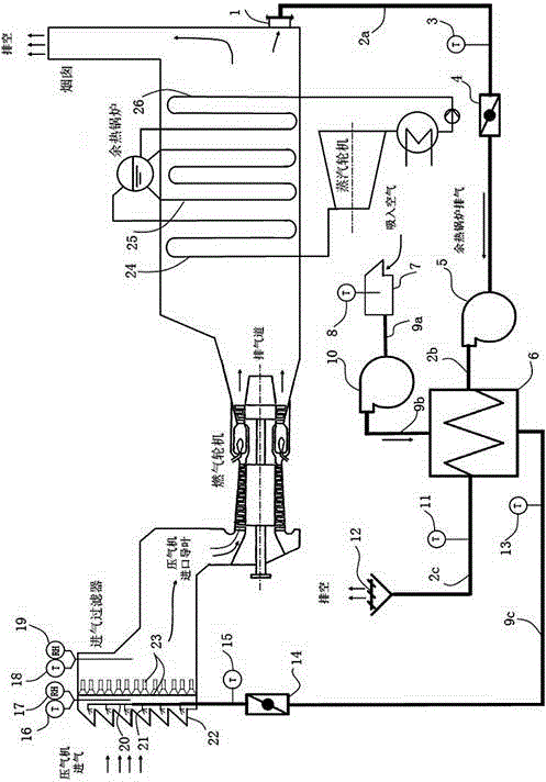
[0040] The gas turbine compressor inlet temperature raising system of the present invention comprises a gas turbine unit (compressor, combustor and turbine), the inlet passage of the gas turbine unit is provided with an intake filter, and the intake filter is arranged in sequence The coarse filter 22 and the fine filter 23 are composed of a thermocouple T between the coarse filter 22 and the fine filter 23 AIN2 16 and hygrometer T RH3 17. After careful consideration of 23, a thermocouple T is set AIN3 18 and hygrometer T RH2 19. The exhaust passage of the gas turbine unit is subsequently jointly equipped with a waste heat steam power generation system. The waste heat steam power generation system includes a waste heat boiler and a steam turbine. The high-temperature gas in the exhaust passage passes through the superheater 24, evaporator 25, and feed water of the waste heat boiler Heater 26 and chimney, its structure such as figure 1 shown.

[0041] The bottom of the chimn...

Embodiment 2

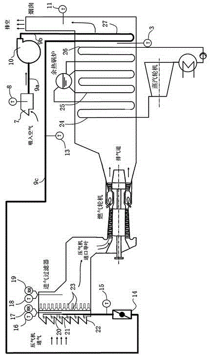
[0047] The gas turbine compressor inlet temperature raising system of the present invention comprises a gas turbine unit (compressor, combustor and turbine), the inlet passage of the gas turbine unit is provided with an intake filter, and the intake filter is arranged in sequence The coarse filter 22 and the fine filter 23 are composed of a thermocouple T between the coarse filter 22 and the fine filter 23 AIN2 16 and hygrometer T RH3 17. After careful consideration of 23, a thermocouple T is set AIN3 18 and hygrometer T RH2 19. The exhaust passage of the gas turbine unit is subsequently jointly equipped with a waste heat steam power generation system. The waste heat steam power generation system includes a waste heat boiler and a steam turbine. The high-temperature gas in the exhaust passage passes through the superheater 24, evaporator 25, and feed water of the waste heat boiler Heater 26 and chimney, its structure such as figure 2 shown.

[0048] A low-temperature air ...

Embodiment 3

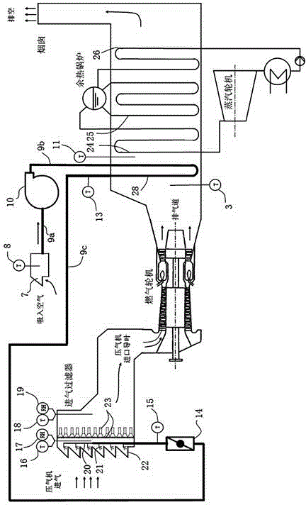
[0055] The gas turbine compressor inlet temperature raising system of the present invention comprises a gas turbine unit (compressor, combustor and turbine), the inlet passage of the gas turbine unit is provided with an intake filter, and the intake filter is arranged in sequence The coarse filter 22 and the fine filter 23 are composed of a thermocouple T between the coarse filter 22 and the fine filter 23 AIN2 16 and hygrometer T RH3 17. After careful consideration of 23, a thermocouple T is set AIN3 18 and hygrometer T RH2 19. At the same time, the exhaust passage of the gas turbine unit can also be selectively installed in conjunction with a waste heat steam power generation system. The waste heat steam power generation system includes a waste heat boiler and a steam turbine. The high-temperature gas in the exhaust passage passes through the superheater 24 of the waste heat boiler, evaporates Device 25, feed water heater 26 and chimney, its structure is as figure 2 sho...


PUM


Abstract

The invention discloses an air suction warming heat exchanging method and an air suction warming heat exchanging system of a gas turbine compressor, and belongs to the technical field of gas turbines. The warming method comprises heating air suction of the gas turbine compressor by using exhaust gas from the gas turbine as the heat source. The warming system comprises a gas turbine unit, wherein an air inlet is provided with an air intake filter; an air vent or an air vent successive afterheat utilizing system is provided with a heat recovering device; a heating device is arranged at the air intake filter; and the heat recovering device and the heating device are combined to form a heat exchanging network. According to the air suction warming heat exchanging method and the air suction warming heat exchanging system of the gas turbine compressor, the exhaust fuel gas from the air vent of the gas turbine is used as the heat source to warm the inlet air from the compressor. The air suction warming method and the air suction warming system improve the air intake temperature of the compressor, achieve the purpose of preventing freezing of a filter element of the air intake filter or freezing of an inlet blade of the compressor, improve the economical efficiency of the warming process, and avoid unfavorable influence on the working condition of the gas turbine by the heat recover of the gas turbine body.

Description

technical field [0001] The invention relates to a heat exchanging method and a heat exchanging network in a gas turbine unit, in particular to a gas turbine compressor intake temperature raising heat exchanging method and a temperature raising heat exchanging system, which belong to the technical field of gas turbines. Background technique [0002] The essence of the gas-steam combined cycle is to superimpose the Brayton Cycle of the gas turbine and the Rankine Cycle of the steam turbine in series to form a combined cycle system. The gas-steam combined cycle combines gas turbines and steam turbines according to the principle of heat cascade utilization, and can utilize high-grade and low-grade heat. It not only takes advantage of the advantages of high average heat absorption temperature of gas turbine cycle and low average heat release temperature of steam turbine cycle, but also overcomes the shortcomings of both, so it can achieve higher cycle efficiency. [0003] A typi...

Claims


Application Information

Patent Timeline
Patent Type & Authority Applications(China)
IPC IPC(8): F02C7/047F02C7/05F02C7/08
Inventor 艾松陶健梁珊珊何瑛陈建
Owner DONGFANG TURBINE CO LTD
Why Eureka
Try Eureka