

Method for measuring medium refractive index
A refractive index and medium technology, applied in the field of refractive index measurement, can solve the problems of inability to measure the refractive index of mm-level samples, inability to measure the refractive index of opaque media, and very high requirements for instrument precision, achieving easy operation, high measurement accuracy, and material selection. handy effect
- Summary
- Abstract
- Description
- Claims
- Application Information
AI Technical Summary
Problems solved by technology
Method used
Image

Examples
Embodiment 1
[0023] Using the method of the present invention, visible light is selected to measure the refractive index of a transparent K9 glass sheet with a thickness of 1 mm.
[0024] (1) Dissolve 0.3g of chalk ash in 10ml of absolute ethanol, the mass volume ratio of the chalk ash to absolute ethanol is 3g / 100ml, shake for 15min to prepare a chalk ash suspension;
[0025] (2) Spin-coat the prepared chalk dust suspension on the surface of the K9 glass sheet, and spin-coat 5 layers until the dust film can be clearly seen on the glass sheet with the naked eye to make a coated glass sheet;
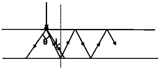
[0026] (3) Put the glass sheet coated with the dust film at the focal point of the lens, make the dust film face the lens, turn on the laser, and focus the laser light on the glass sheet coated with the dust film through the lens, and you can see clearly on the dust film halo;
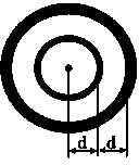
[0027] (4) The measured inner radius difference between adjacent halos is ;
[0028] (5) Substitute into the formula ,...
Embodiment 2
[0031] Using the method of the present invention, infrared light with a wavelength of 980nm is selected to measure the refractive index of polysilicon (gray opaque) with a thickness of 3mm. Replace the chalk dust in Example 1 with infrared fluorescent powder, and replace the organic solvent absolute ethanol with acetone, and the rest of the steps are the same. Measure the inner radius of the first halo ;Into the formula , The calculated refractive index of the measured polysilicon is 3.481.
[0032] Prior art: The refractive index of the sample is measured by an infrared interferometer to be 3.485, which is consistent with the experimental results.
[0033]
Embodiment 3
[0035] By adopting the method of the present invention, ultraviolet light with a wavelength of 320nm is selected to measure the refractive index of an opaque and ultraviolet transparent plastic sheet in the visible wave band with a thickness of 1mm. The chalk dust in Example 1 was replaced with ultraviolet-excited fluorescent powder, the organic solvent absolute ethanol was replaced with toluene, and the rest of the steps remained unchanged. The result was measured ;Into the formula , the calculated refractive index of the measured plastic sheet is 1.667.
PUM
| Property | Measurement | Unit |
|---|---|---|
| Thickness | aaaaa | aaaaa |
Abstract
Description
Claims
Application Information