Three-phase photovoltaic inversion device based on transformer cascading technology

A photovoltaic inverter and transformer technology, which is applied in the direction of output power conversion devices, photovoltaic modules, photovoltaic power generation, etc., can solve the difficulty in realizing the manufacturing process of phase-shifting transformers and reduce the manufacturing cost of high-power centralized photovoltaic grid-connected inverter systems , unable to achieve PWM voltage regulation and other problems, to achieve the effect of overcoming the inability to realize PWM voltage regulation, significant cost advantages, easy modularization and standardization

Inactive Publication Date: 2015-01-28
TBEA XIAN ELECTRIC TECH +1
View PDF3 Cites 14 Cited by
  • Summary
  • Abstract
  • Description
  • Claims
  • Application Information

AI Technical Summary

Problems solved by technology

[0005] In order to solve the problems existing in the above-mentioned prior art, the object of the present invention is to provide a three-phase photovoltaic inverter device based on transformer cascading technology, which solves the PID effect of non-isolated cascaded inverter PV components and the common problem of PV components. The problem of mold leakage current overcomes the problem that multiple technologies cannot realize PWM voltage regulation in the application of photovoltaic grid-connected systems, and the problem that the manufacturing process of phase-shifting transformers is not easy to realize, and reduces the cost of high-power centralized photovoltaic grid-connected inverter systems. manufacturing cost

Method used


Image

  • Three-phase photovoltaic inversion device based on transformer cascading technology
  • Three-phase photovoltaic inversion device based on transformer cascading technology
  • Three-phase photovoltaic inversion device based on transformer cascading technology

Examples


Embodiment Construction

[0025] The present invention will be further described in detail below in conjunction with the accompanying drawings and specific embodiments.

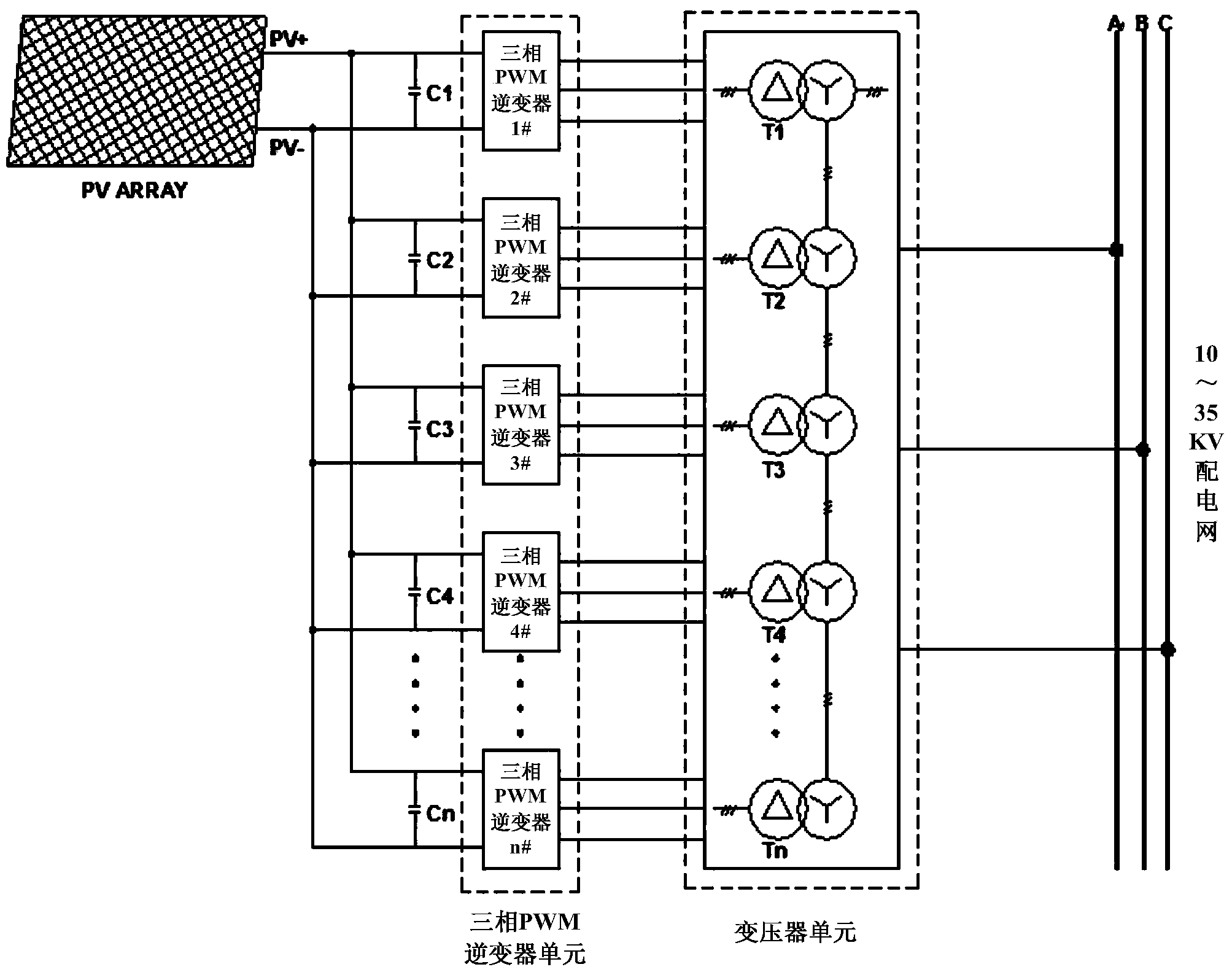
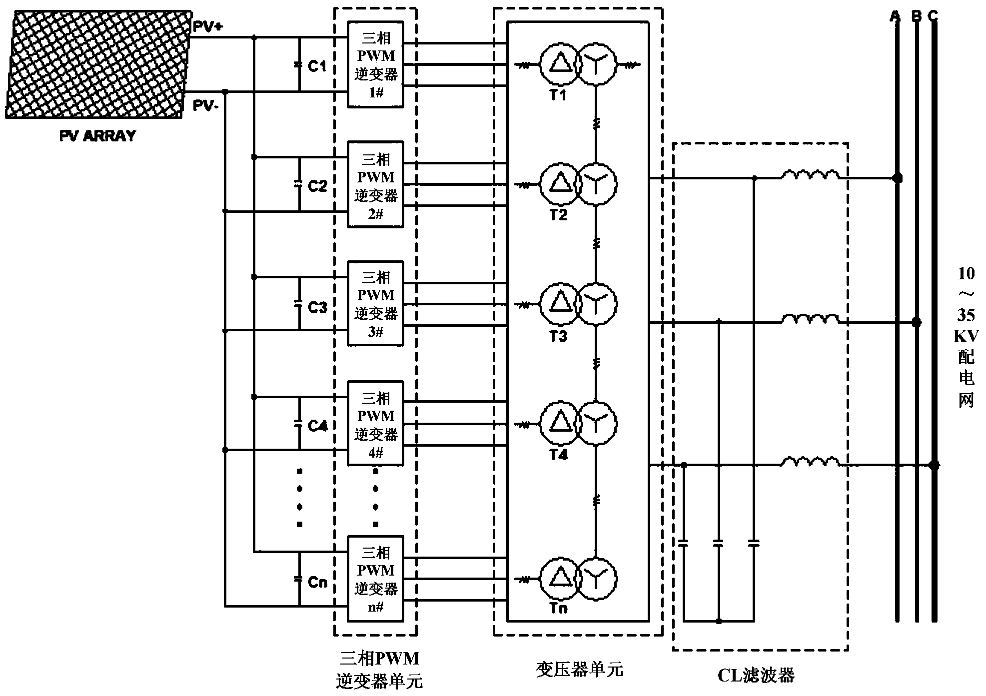
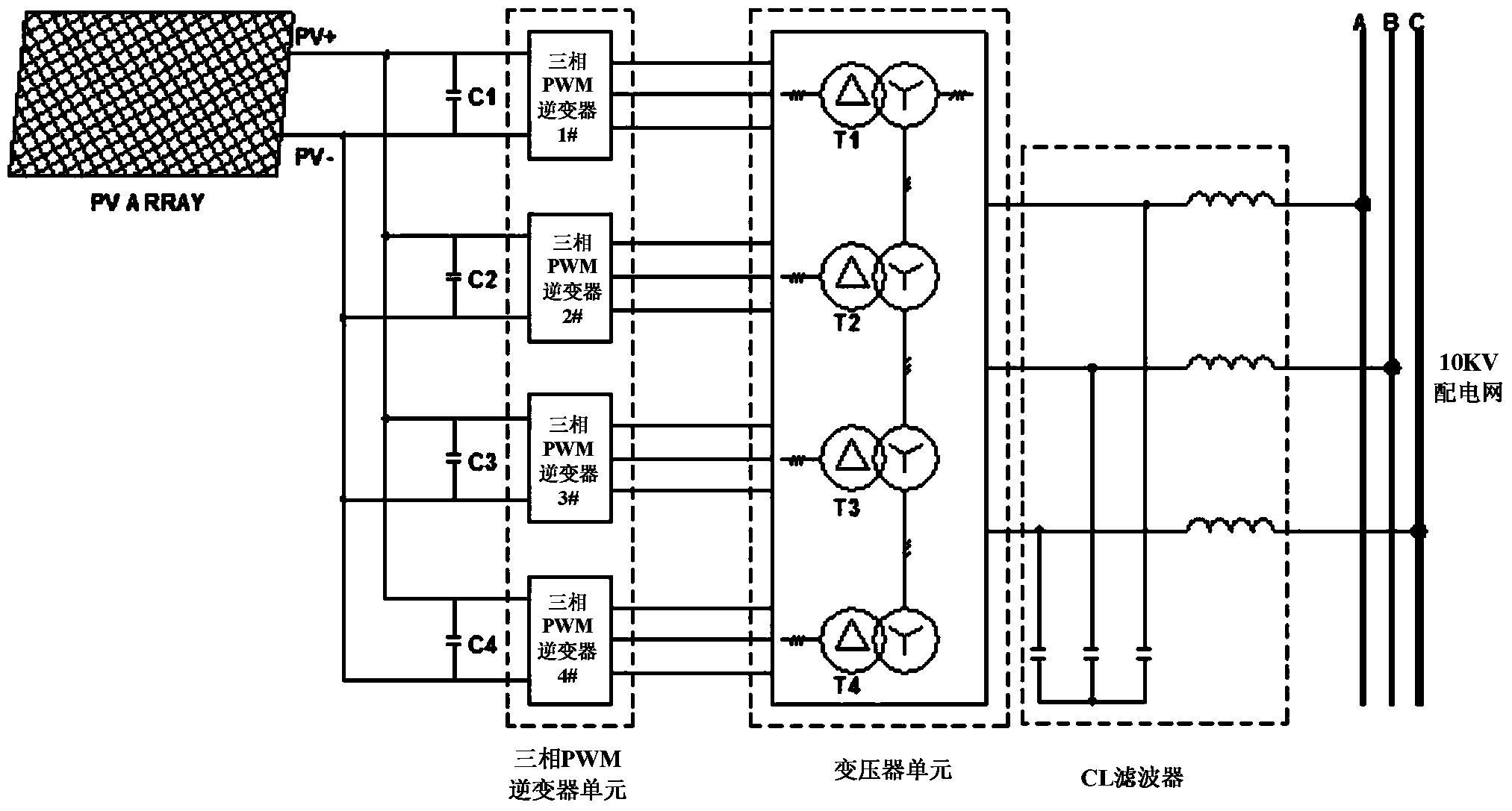
[0026] Such as figure 1 As shown, the present invention is a three-phase photovoltaic inverter device based on transformer cascading technology. The DC side of the three-phase photovoltaic inverter device uses a group of photovoltaic arrays as the DC source input, and the output terminals of the photovoltaic arrays are connected in parallel with multiple Photovoltaic inverter unit branches, the output ends of the plurality of photovoltaic inverter unit branches are connected in series in sequence, and the output ends after series connection are directly merged into the medium-voltage power grid; the input ends of each photovoltaic inverter unit branch A group of bus capacitors are connected in parallel, and the output terminals of the bus capacitors are connected to the input terminals of the photovoltaic inverter unit; the photovolta...


PUM


Abstract

The invention provides a three-phase photovoltaic inversion device based on the transformer cascading technology. A photovoltaic array is adopted on the direct current side of the inversion device to serve as direct current source input, multiple photovoltaic inversion unit branches are connected to the output end of the photovoltaic array in parallel, the output ends of the photovoltaic inversion unit branches are sequentially connected in series, and the output ends connected in series are directly combined in a medium-voltage power grid. The input end of each photovoltaic inversion unit branch is connected with a bus capacitor in parallel, and the output ends of the bus capacitors are connected with the input end of a photovoltaic inversion unit. The photovoltaic inversion unit is formed by connecting three-phase PWM inverters and transformers in series, the input ends of the three-phase PWM inverters are the input ends of the photovoltaic inversion unit branches, the output ends of the three-phase PWM inverters are connected with primary side windings of the transformers, and secondary side windings of the transformers serve as the output ends of the branches and are in series connection with the output ends of other branches connected in parallel. Compared with traditional phase-shifting transformers, the transformers used in the device have the advantages that the manufacturing process is simplified and the manufacturing cost of a high-power centralized photovoltaic grid-connected inversion system is reduced.

Description

technical field [0001] The invention relates to the technical field of photovoltaic inverters, in particular to a three-phase photovoltaic inverter device based on transformer cascading technology. Background technique [0002] In order to increase the stand-alone capacity of photovoltaic inverters, most high-power grid-connected inverters adopt multi-level methods. The main purpose of adopting multilevel inverter is to realize high voltage output by using low withstand voltage switching devices. Both the cascade method and the multiple superposition method are the main methods to generate multilevel inverters. The cascading method is to take N H bridges (inversion units) with independent DC sources and output voltages of SPWM waves, shift their triangular carrier waves by 2π / N in turn, and directly superimpose the output voltages of the H bridges in series, so that The output voltage becomes a SPWM multi-level ladder wave to achieve the purpose of eliminating carrier harm...

Claims


Application Information

Patent Timeline
Patent Type & Authority Applications(China)
IPC IPC(8): H02J3/38H02J3/01H02S40/32H02M7/5387
CPCH02J3/383H02J3/01H02M7/493H02S40/00Y02E10/56Y02E40/40
Inventor 刘小刚姜耀军张新涛张磊
Owner TBEA XIAN ELECTRIC TECH
Why Eureka
Try Eureka