Device for moving small insulating plate at bottom of polycrystalline silicon ingot furnace and polycrystalline silicon ingot furnace

A polysilicon ingot casting furnace and movable device technology, which is applied in post-processing devices, polycrystalline material growth, crystal growth, etc., can solve the problems of reduced solidification speed of ingots, increased cost of silicon wafers, diffusion pollution, etc., and achieves improved cooling and crystallization Speed, shorten production cycle, reduce the effect of production cost

Inactive Publication Date: 2015-02-04
吕铁铮
View PDF5 Cites 3 Cited by
  • Summary
  • Abstract
  • Description
  • Claims
  • Application Information

AI Technical Summary

Problems solved by technology

However, since the size of the furnace body remains unchanged after the transformation, the weight of the ingot after the transformation increases by 44% and 96% respectively, and the heat dissipation capacity at the bottom of the thermal field needs to be improved accordingly. The heat dissipation capacity of the existing heat insulation cage lifting technology is only slightly improved, so the It will greatly reduce the solidification rate during the ingot casting process
For example, the solidification time of G5 ingot is about 25 hours, but the solidification time of G6 ingot is about 40 hours, and the solidification time of G7 ingot is longer
This virtually increases the cost of silicon wafer production, and at the same time, during the solidification process, most of the silicon material is still in a high-temperature melting state, which also increases the risk of silicon leakage
In addition, due to the long contact time between the silicon ingot and the crucible, it will also cause a certain diffusion pollution of oxygen, which will reduce the quality of the crystal.
[0005] At present, the bottom insulation plate of G5, G6, and G7 is a whole plate. The heat at the bottom of the crucible is more difficult to radiate than the heat at the edge of the crucible during crystal growth, resulting in a slightly concave solid-liquid interface during crystal growth. Impurities in the silicon melt will be deposited in the middle, so that the quality of the grown crystals is low, and the conversion efficiency of the cut silicon wafers is also low
At the same time, for the larger G6 type (about 800 kg) and G7 type (about 1200 kg) polycrystalline ingots, the latent heat of crystallization is huge. According to the current heat insulation cage radiation heat dissipation method, it is difficult to effectively dissipate the latent heat of crystallization.

Method used


Image

  • Device for moving small insulating plate at bottom of polycrystalline silicon ingot furnace and polycrystalline silicon ingot furnace
  • Device for moving small insulating plate at bottom of polycrystalline silicon ingot furnace and polycrystalline silicon ingot furnace
  • Device for moving small insulating plate at bottom of polycrystalline silicon ingot furnace and polycrystalline silicon ingot furnace

Examples


Embodiment 1

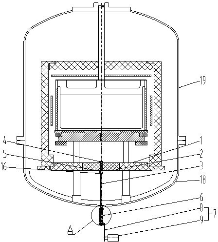
[0037]The present embodiment comprises bottom small insulation board 2, support rod 3, telescopic tube 6, lifting device 7; The bottom small insulation board 2 is fixed on the top of support rod 3 with upper nut 4 and lower nut 16; Stretch to telescopic tube 6 bottoms; Telescopic tube 6 upper ends link to each other with body of heater, telescopic tube 6 lower ends are connected with elevating device 7; (Such as figure 1 shown);

[0038] Elevating device 7 is made up of elevating rod 8 and servo motor 9, and elevating rod 8 can move up and down along servo motor 9, thereby drives the bottom small insulation board 2 of support rod 3 tops to move up and down.

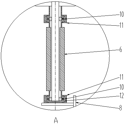
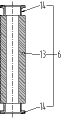
[0039] The telescopic tube 6 is sealed and welded by the bellows 13 and the quick-change joint 14; the upper end of the telescopic tube 6 is connected to the furnace body with a sealing ring 10, which can be sealed and fixed with a clamp 11; the lower end of the telescopic tube 6 is connected to the blind plate 12 A sea...

Embodiment 2

[0049] The difference between this embodiment and Embodiment 1 is only that: the support rod 3 is a tungsten rod; Figure 8 As shown), the cross-section of the bottom large insulation board 1 corresponding to the matching hole is circular; when the melting is completed and enters the crystal growth stage, start the lifting device 7 to separate the bottom small insulation board 2 from the bottom large insulation board 1, and the separation distance is 15 is 60mm. The rest are the same as embodiment 1.

[0050] Taking GT polysilicon ingot furnace G5 transformed into G6 as an example, the weight of the ingot is increased from 500 kg to 800 kg. If the crystal growth plan of lifting the heat insulation cage is simply adopted, the crystal growth time will take about 40 hours, and the total The process time is 75 hours; and after adopting the movable device of the small insulating plate at the bottom of the polysilicon ingot furnace of the present invention, the crystal growth time ...

Embodiment 3

[0052] The difference between this embodiment and Embodiment 1 is that: the support rod 3 is an iridium rod; the upper nut 4, the lower nut 16 and the backing plate 5 are made of carbon-carbon composite material; the lifting device 7 is replaced by a C-shaped card 20, when When melting completes and enters the crystal growth stage, use the C-shaped card 20 to separate the small insulation board 2 at the bottom from the large insulation board 1 at the bottom, and the separation distance 15 is 100mm (such as Figure 5 , Figure 6 shown). The rest are the same as embodiment 1.

[0053] Taking JYT polysilicon ingot furnace G5 transformed into G7 as an example, the weight of the ingot is increased from 500 kg to 1200 kg. If the crystal growth plan is simply adopted by the heat insulation cage, the crystal growth time will take about 52 hours, and the total The process time is 90 hours; and after adopting the movable device of the small insulating plate at the bottom of the polysi...


PUM


Abstract

The invention discloses a device for moving a small insulating plate at the bottom of a polycrystalline silicon ingot furnace and the polycrystalline silicon ingot furnace. The moving device comprises a small bottom insulating plate (2), a supporting rod (3), a telescopic pipe (6) and a lifting device (7), wherein the small bottom insulating plate (2) is fixedly arranged at the upper part of the supporting rod (3) by using an upper nut (4) and a lower nut (6); the lower part of the supporting rod (3) penetrates to the bottom of the telescopic pipe (6); the upper end of the telescopic pipe (6) is connected with a furnace body; the lower end of the telescopic pipe (6) is connected with the lifting device (7); the small bottom insulating plate (2) can move up and down under the control of the lifting device (7). By unique structural design, the device disclosed by the invention can be used for making the small bottom insulating plate (2) move downwards to be separated from a large bottom insulating plate (1) when crystal starts to grow in the furnace and quickening cooling of a core part of a coagulated piece so that cooling and crystallization speed of silicon melt in a crucible can be increased; meanwhile, a considerable super-cooling degree of the silicon melt is formed, and the quality of an polycrystalline silicon ingot is improved.

Description

technical field [0001] The invention relates to a polysilicon ingot furnace, in particular to a small heat preservation board movable device at the bottom of the polysilicon ingot furnace, and a polysilicon ingot furnace including the small heat insulation board movable device at the bottom. technical background [0002] The growth of silicon crystals is generally divided into three methods: polycrystalline ingot, single crystal pulling and zone melting growth. With the large-scale application of crystalline silicon photovoltaic products, the solar-grade crystalline silicon wafer industry continues to develop and mature. The price of raw materials is gradually falling rationally, which also causes the continuous compression of the profit margin of silicon wafer manufacturers. Improving the quality of silicon wafers and reducing processing costs have become issues facing all solar silicon wafer manufacturers. The industrial chain of crystalline silicon photovoltaic power gen...

Claims


Application Information

Patent Timeline
IPC IPC(8): C30B28/06C30B29/06
CPCC30B35/00
Inventor 吕铁铮
Owner 吕铁铮
Why Eureka
Try Eureka