
Vacuum Noise Isolation System for Lithography Equipment

A technology of isolation system and lithography equipment, which is applied in the field of vacuum noise isolation system, can solve the problems of not being able to use rubber seals, not resistant to baking and outgassing, and low reliability of implementation, so as to improve precision, reduce noise, The effect of improving accuracy

Active Publication Date: 2017-12-29
SHANGHAI MICRO ELECTRONICS EQUIP (GRP) CO LTD
View PDF5 Cites 1 Cited by
  • Summary
  • Abstract
  • Description
  • Claims
  • Application Information

AI Technical Summary

Problems solved by technology

However, the structure of the scheme is too complicated and the reliability of implementation is low.
General characteristics of metal seals The main disadvantage of rubber seals is that they are not resistant to baking and have a large amount of outgassing at room temperature, so many require high-temperature baking (>200 degrees Celsius) and only use low vapor pressure (vapor pressure at room temperature<10^- 10 Pa) materials for ultra-high vacuum system devices, cannot use rubber seals, but need to be sealed with metal seals

Method used


Image

  • Vacuum Noise Isolation System for Lithography Equipment
  • Vacuum Noise Isolation System for Lithography Equipment
  • Vacuum Noise Isolation System for Lithography Equipment

Examples


Embodiment Construction

[0033] Specific embodiments of the present invention will be described in detail below in conjunction with the accompanying drawings. The technical terms that will be used in the present invention are as follows:

[0034] Light source system, Source, SO

[0035] The terms "radiation" and "beam" as used herein encompass all types of electromagnetic radiation including: ultraviolet (UV) radiation (e.g. having a wavelength of about 365, 248, 143, 157 or 126 nm), and particle beams, such as ion beams or electron beam.

[0036] Illumination System, Illuminator, ILL

[0037] The illumination system may include various types of optical components, such as refractive, reflective, magnetic, electromagnetic, electrostatic, or other types of optical elements, or combinations of all of these elements, to direct, shape, or steer the radiation beam .

[0038] The illuminator ILL receives the radiation beam emitted from the radiation source SO. The source and the lithographic apparatus ...


PUM


Abstract

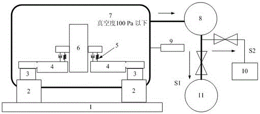
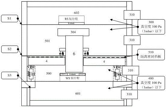
The present invention provides a vacuum noise isolation system for lithography equipment, which is characterized in that it includes: a vacuum cavity, which at least includes the mask, projection objective lens and workpiece of the lithography equipment; A device is used to pump air to the vacuum cavity; a vacuum detection device is used to monitor the vacuum degree of the vacuum cavity in real time; a shape memory alloy metal sealing ring is used to seal the vacuum cavity.

Description

technical field [0001] The invention relates to the field of integrated circuit equipment manufacturing, in particular to a vacuum noise isolation system for photolithography equipment. Background technique [0002] A lithographic apparatus is a machine that applies a desired pattern to a substrate, usually a target portion of the substrate. For example, lithographic equipment may be used in the manufacture of integrated circuits (ICs). In this case, a patterning device, alternatively referred to as a mask or reticle, may be used to generate a circuit pattern corresponding to a single layer of the IC. The pattern can be imaged onto a target portion (eg, comprising a portion, one or more dies) on a substrate (eg, a silicon wafer). Pattern imaging is performed by imaging the pattern onto a layer of radiation sensitive material (resist) provided on the substrate. Typically, a single substrate will contain a network of adjacent target portions that are sequentially exposed. ...

Claims


Application Information

Patent Timeline
Patent Type & Authority Patents(China)
IPC IPC(8): G03F7/20
Inventor 吴飞钟亮彭巍王茜俞芸王璟
Owner SHANGHAI MICRO ELECTRONICS EQUIP (GRP) CO LTD
Learn More