Confocal-scanning microscopic imaging method and system based on laser heterodyne interferometry

A technology of optical heterodyne interference and scanning microscopy, which is used in material analysis by optical means, measurement of phase influence characteristics, instruments, etc. It can solve samples that cannot obtain quantitative phase information, cannot be resolved by confocal microscopy, and have birefringence characteristics. detection and other problems, to achieve the effect of increasing the detectable depth, realizing high-resolution measurement, and improving the axial resolution

Active Publication Date: 2015-02-18
GUANGDONG OPTO MEDIC TECH CO LTD
View PDF9 Cites 17 Cited by
  • Summary
  • Abstract
  • Description
  • Claims
  • Application Information

AI Technical Summary

Problems solved by technology

[0009] The above two phase methods avoid the use of fluorescent dyes. However, the laser oblique illumination microscopic imaging method needs to adjust the angle between the detection light path and the incident light path, so it is difficult to achieve phase measurement without destroying the original confocal light path. would result in the need to substantially modify the original microscope structure to use this technique
The differential interference phase contrast microscopy imaging method needs to add an additional polarizing element in the optical path to generate polarized light, and use the shear angle formed by the two polarized lights for phase difference detection. The Wollaston prism used is expensive and cannot detect Samples with refractive properties are detected, which limits the scope of use
At the same time, neither of these two methods can obtain quantitative phase information accurate to one thousandth of a radian
[0010] In addition, there are micron-scale light waists in the focus point of the confocal microscope in each of the above processing methods. In this range, the confocal microscope cannot distinguish

Method used


Image

  • Confocal-scanning microscopic imaging method and system based on laser heterodyne interferometry
  • Confocal-scanning microscopic imaging method and system based on laser heterodyne interferometry
  • Confocal-scanning microscopic imaging method and system based on laser heterodyne interferometry

Examples


Embodiment Construction

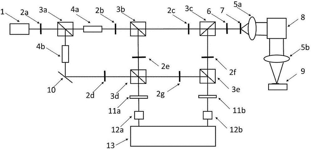
[0042] Such as figure 1 , the specific embodiment of the present invention comprises a laser light source part, a frequency shift part, a confocal scanning part, an optical signal acquisition part and a signal analysis part;

[0043] The laser light source includes a laser 1 that outputs a single-wavelength laser, a half-wave plate 2a, and a polarization beam splitter 3a that splits the laser into two laser beams;

[0044] The frequency shift part includes a local oscillator optical transmission optical path and a signal optical transmission optical path. The local oscillator optical transmission optical path is provided with a first acousto-optic frequency shifter 4b with adjustable frequency, a transmitting mirror 10 for adjusting the optical transmission direction of the local oscillator, and a half-wave plate 2d, local oscillator optical polarization beam splitter 3d, half-wave plate 2g; signal light transmission optical path is provided with a second acousto-optic frequen...


PUM


Abstract

The invention discloses a confocal microscopic imaging system based on the laser heterodyne interferometry. The confocal microscopic imaging system is characterized in that on the basis of a microscope optical system and a scanning part of the existing laser confocal microscope, a frequency-shifting part is added, and accurate measurement is realized by combination of the optical heterodyne interferometry. The confocal microscopic imaging system disclosed by the invention has the advantages that the ultrahigh lateral resolution of a confocal scanning microscope is fully utilized, and simultaneously accurate phase information is acquired for replacing intensity information, so that not only is the axial resolution increased, but also a series of problems brought by use of a fluorescent dye are avoided; and a transparent phase object can be measured under the condition without marks.

Description

technical field [0001] The invention relates to a confocal scanning microscopic imaging method, which belongs to the field of optical precision measurement, in particular to a confocal scanning microscopic imaging method based on optical heterodyne interferometry, and also relates to a system using the above method. Background technique [0002] Laser scanning confocal microscope (LSCM) is a major improvement over ordinary optical microscopes. It is mainly composed of the following four parts: microscope optical system; scanning device. The scanning device used by LSCM is generally mirror scanning in the biological field; Laser light source; detection system. The basic idea was proposed by M.Minsky in 1957. Different from general microscopic imaging, it adds a detection pinhole conjugated to the object point in the optical path, which plays a role of spatial filtering. In the case of using fluorescent dyes, It can remove the interference of out-of-focus fluorescence, genera...

Claims


Application Information

Patent Timeline
Patent Type & Authority Applications(China)
IPC IPC(8): G01N21/45G01N21/01
Inventor 王翰林刘满林刘俊安昕张浠
Owner GUANGDONG OPTO MEDIC TECH CO LTD
Why Eureka
Try Eureka