
Backlight module and liquid crystal display device

A technology of backlight module and liquid crystal display, applied in instruments, optics, nonlinear optics, etc., can solve the problems of reducing the ability of excited light, limiting the life of the backlight module, thick thickness of the backlight module, etc., to improve the uniformity , Simplify the structure and ensure the effect of life

Active Publication Date: 2015-02-18
BOE TECH GRP CO LTD +1
View PDF6 Cites 8 Cited by
  • Summary
  • Abstract
  • Description
  • Claims
  • Application Information

AI Technical Summary

Problems solved by technology

Specifically, the fluorescent powder is made by dispensing glue on the bracket containing the LED. The backlight module with this structure has the following two disadvantages: one is that the fluorescent powder and the glue directly contact the LED after fusion, and the LED is in the process of working. Due to heat generation, the junction temperature is kept at a high temperature for a long time, which causes the phosphor to be affected by the heat accumulation of the junction temperature, reduces its ability to be excited by light, further leads to brightness attenuation, and limits the life of the backlight module; the other is LED and phosphor The powder is a point-to-point structure, so that the light emitted by the entire LED is also a point light source. Therefore, it is generally necessary to further improve the scattering of the dot matrix light source through components such as a diffuser plate and an optical diffuser to improve the uniformity of the dot matrix light source. As a result, the entire backlight module The thickness of the group is thicker

Method used


Image

  • Backlight module and liquid crystal display device
  • Backlight module and liquid crystal display device
  • Backlight module and liquid crystal display device

Examples


Embodiment Construction

[0026] The specific implementation manners of the backlight module and the liquid crystal display device provided by the embodiments of the present invention will be described in detail below with reference to the accompanying drawings.

[0027] The shape and size of each film layer in the drawings do not reflect the real proportion of the backlight module, and the purpose is only to illustrate the content of the present invention.

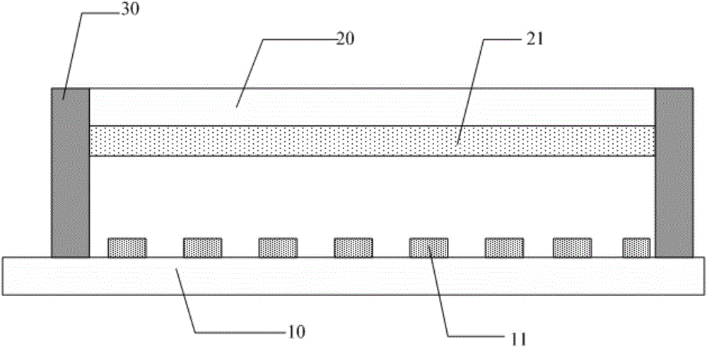
[0028] A backlight module provided by an embodiment of the present invention, such as figure 2 As shown, it includes: a first substrate 10 and a second substrate 20 arranged oppositely, an array of light emitting devices 11 located on the first substrate 10, and a driving circuit for driving the light emitting devices 11 to emit light ( figure 2 not shown in ), the phosphor layer 21 coated on the side of the second substrate 20 facing the first substrate 10, and the sealant frame 30 sealingly connecting the boundary of the first substrate 10 and...


PUM


Abstract

The invention discloses a backlight module and a liquid crystal display device. According to the backlight module, a fluorescent powder layer and a luminescent device are respectively arranged on two substrates which are oppositely arranged, and the fluorescent powder layer and the luminescent device are separately arranged, so that, compared with the prior art that fluorescent powder is directly coated on the luminescent device, the back module has the advantage that the effect on the fluorescent powder due to the heat of the luminescent device when the backlight module emits light can be lowered, so as to ensure the service life of the backlight module. The fluorescent powder layer is evenly coated on the second substrate; each point on the fluorescent powder layer can be bombarded by electrons from an array of the luminescent device and photons generated by holes in the compound process to emit light; the uniformity of the luminous surface is improved to the greatest extent; the light emitted by the luminescent device is evenly emergent through the fluorescent powder layer, thus the arrangement of a light guide plate and an optical diffusion sheet in the prior art can be omitted; the thickness of the backlight module is lowered; the structure of the backlight module is simplified.

Description

technical field [0001] The invention relates to the field of display technology, in particular to a backlight module and a liquid crystal display device. Background technique [0002] A liquid crystal display device is a passive light-emitting device, which does not emit light itself, and requires a backlight module to provide a light source for the liquid crystal panel to display images. Since the backlight module used on the liquid crystal panel has the characteristics of thinness and power saving, it is widely used in display devices. [0003] Currently, backlight module technologies mainly used in liquid crystal display devices are: cold cathode tube (Cold Cathode Fluorescent Lamp, CCFL) and light emitting diode (Light Emitting Diodes, LED). [0004] Because LED backlight modules have many advantages such as high brightness, high color purity, long life, good reliability, and no mercury pollution, the proportion of LED backlight modules gradually increases. [0005] Ac...

Claims


Application Information

Patent Timeline
IPC IPC(8): G02F1/13357
CPCG02F1/133602G02F1/133609G02F1/133614
Inventor 陈秀云廖燕平尹大根
Owner BOE TECH GRP CO LTD
Features
  • Generate Ideas
  • Intellectual Property
  • Life Sciences
  • Materials
  • Tech Scout
  • Unparalleled Data Quality
  • Higher Quality Content
  • 60% Fewer Hallucinations
Learn More