Ultra-wideband variable gain amplifier

A gain amplifier and ultra-broadband technology, applied in amplifiers, amplifiers with only semiconductor devices, amplifiers with semiconductor devices/discharge tubes, etc., can solve the problems of unfavorable integration, GaAs process incompatibility, high cost, etc., and achieve good power Efficiency, good linearity, effect of reducing power consumption

Active Publication Date: 2015-02-18
BEIJING UNIV OF TECH
View PDF4 Cites 2 Cited by
  • Summary
  • Abstract
  • Description
  • Claims
  • Application Information

AI Technical Summary

Problems solved by technology

However, the GaAs process is not compatible with the mature Si planar process, which is not conducive to integration and high cost

Method used


Image

  • Ultra-wideband variable gain amplifier
  • Ultra-wideband variable gain amplifier
  • Ultra-wideband variable gain amplifier

Examples


Embodiment Construction

[0020] In order to make the object, technical solution and advantages of the present invention clearer, the present invention will be further described in detail below in conjunction with the accompanying drawings. However, the examples given are not intended to limit the present invention.

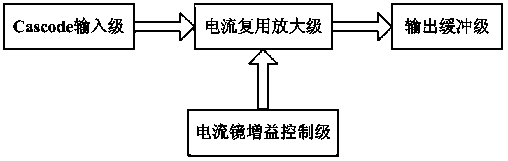
[0021] Such as figure 1 As shown, the implementation of the present invention includes four parts: a Cascode input stage, a current multiplexing amplifier stage, an output buffer stage, and a current mirror gain control stage.

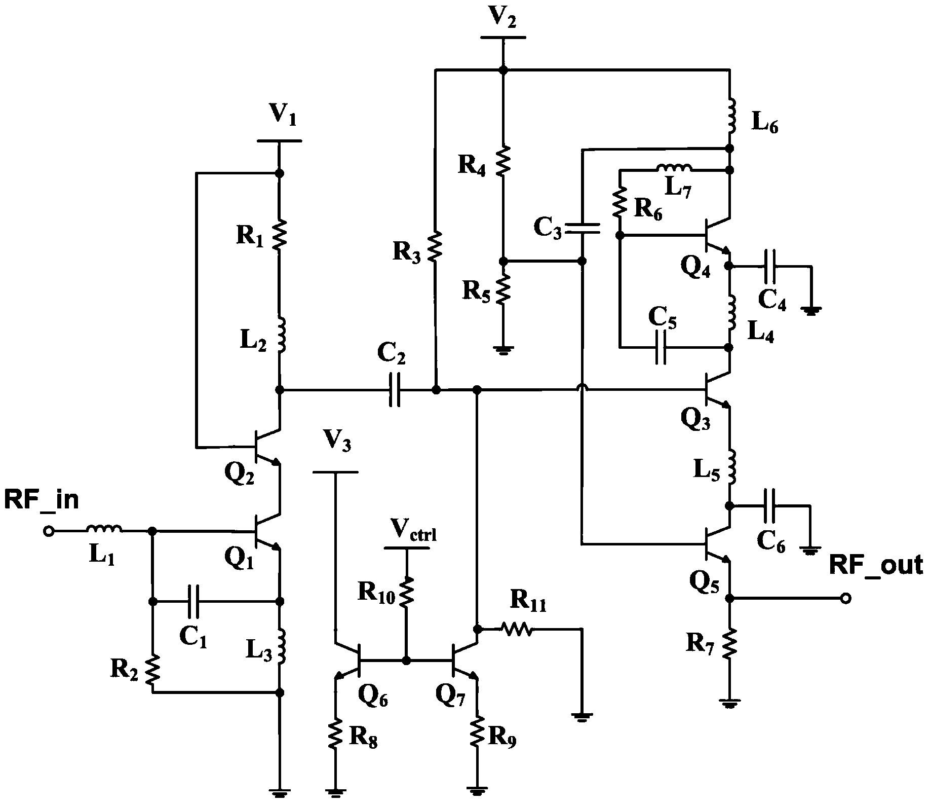
[0022] Such as figure 2 As shown, Cascode input stage: heterojunction bipolar transistor Q 1 and Q 2 Constitute the Cascode structure; R 1 , L 2 and bias voltage V 1 Provides a bias for the Cascode structure; R 2 , C 1 , L 1 and L 3 Form a matching network to achieve input matching and noise matching. where V 1 = 1.2V, R 1 =920Ω,R 2 = 5Ω, L 1 =0.9nH, L 2 =3.3nH,L 3 =0.9nH, =C 1 = 0.26pF, V 1 = 1.2V.

[0023] Such as figure 2 As shown, the cu...


PUM


Abstract

The invention discloses an ultra-wideband variable gain amplifier and relates to the technical field of radio frequency integrated circuits. The amplifier comprises a Cascode input stage, a current multiplexing amplification stage, an output buffer stage and a current mirror gain control stage. By virtue of a Cascode structure, input matching and noise matching are realized, and meanwhile, high gain is obtained. The amplification stage is connected with the output buffer stage by virtue of a two-stage current multiplexing structure, so that the power consumption of the amplifier is effectively reduced. By virtue of a current mirror gain control structure, gain controllability is achieved, and meanwhile, a circuit is high in linearity and high in power efficiency.

Description

technical field [0001] The invention relates to the technical field of radio frequency integrated circuits, in particular to an ultra-wideband variable gain amplifier. Background technique: [0002] A variable gain amplifier is one of the core components in the front end of an RF receiver. The transmission environment of the wireless communication system is complex and changeable. In order to ensure the accuracy of data transmission, it is necessary to use a variable gain amplifier in the wireless receiver to process the received signals of different amplitudes to maintain a stable signal output of the receiver. [0003] In terms of integrated circuit technology, most of the research on VGA at home and abroad is realized by GaAs technology and CMOS technology. However, the GaAs process is not compatible with the mature Si planar process, which is not conducive to integration and high cost. The CMOS process is mature and the device cost is low. But suitable for low frequen...

Claims


Application Information

Patent Timeline
Patent Type & Authority Applications(China)
IPC IPC(8): H03F3/04H03G3/20
CPCH03F1/0205H03F1/3205H03F3/165H03F2200/372H03G1/0029
Inventor 谢红云张良浩刘硕张万荣赵飞义邓蔷薇江之韵
Owner BEIJING UNIV OF TECH
Why Eureka
Try Eureka