Eureka AIR delivers breakthrough ideas for toughest innovation challenges, trusted by R&D personnel around the world.

Microwave frequency source device for Raman laser system of atom interferometer

A Raman laser and microwave frequency technology, applied in the field of frequency sources, can solve the problems of low phase noise performance of output signals, reduce the utilization rate of signal generators, limit the performance of Raman laser systems, etc., to improve practicability and mobility , reduce phase noise and improve coherence

Inactive Publication Date: 2015-02-25
BEIHANG UNIV
View PDF1 Cites 13 Cited by
  • Summary
  • Abstract
  • Description
  • Claims
  • Application Information

AI Technical Summary

Problems solved by technology

At present, most of the general-purpose commercial microwave signal generators are broadband signal generators, and the frequency range is from 1 kHz to more than a dozen or more than 20 GHz. This inevitably results in low phase noise performance of the output signal. If applied to Raman In the laser system, it will limit the performance of the Raman laser system
In addition, the Raman laser system only needs a broadband microwave signal generator to output a single point frequency, which greatly reduces the utilization rate of the signal generator, and the signal generator is expensive, with a large volume and power consumption, which greatly reduces the power consumption of this solution. practicality and mobility

Method used


Image

  • Microwave frequency source device for Raman laser system of atom interferometer
  • Microwave frequency source device for Raman laser system of atom interferometer

Examples


Embodiment Construction

[0022] The present invention will be further described in detail with reference to the accompanying drawings and embodiments.

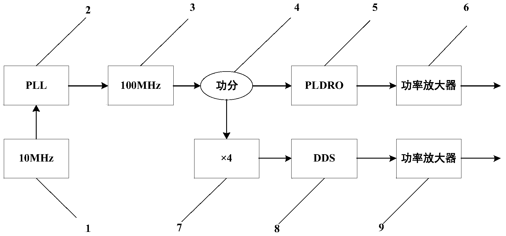
[0023] The present invention is a microwave frequency source device for a Raman laser system, such as figure 1 As shown, including ultra-low phase noise 10MHz constant temperature crystal oscillator 1, phase-locked loop PLL2, 100MHz voltage-controlled crystal oscillator 3, power divider 4, phase-locked dielectric oscillator 5, low-noise power amplifier 6, frequency quadrupler 7, Direct digital synthesizer DDS8, low noise power amplifier 9.

[0024] The 100MHz voltage-controlled crystal oscillator 3 is locked to the 10MHz constant temperature crystal oscillator 1 with ultra-low phase noise through the phase-locked loop PLL2, which can reduce the phase noise of the 100Mz voltage-controlled crystal oscillator 3 and improve frequency stability. The locked 100MHz output signal is divided into two paths by the power divider 4, and one path is amplified by ...


PUM


Abstract

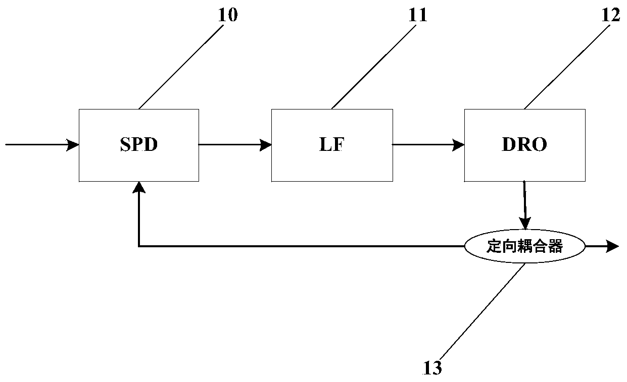
The invention discloses a microwave frequency source device for a Raman laser system of an atom interferometer. The microwave frequency source device comprises a constant-temperature crystal oscillator, a phase-locked loop (PLL), a voltage-controlled crystal oscillator, a power divider, a phase-locked medium oscillator, a first low-noise power amplifier, a quadrupler, a direct digital synthesizer (DDS) and a second low-noise power amplifier. The voltage-controlled crystal oscillator is locked to the ultralow-phase-noise constant-temperature crystal oscillator through the PLL and then divided into two paths through the power divider, one path undergoes frequency amplification through the phase-locked medium oscillator and power amplification through the first power amplifier, and the other path is processed by the quadrupler and then undergoes frequency conversion through the DDS and power amplification through the second power amplifier. By adopting the DDS and the sampling phase-locked medium oscillator, the phase noise of the Raman laser system is effectively lowered; by adopting the ultralow-phase-noise crystal oscillator to provide a reference signal, the size and the power consumption of a microwave frequency source are reduced, and the practicability and motility are improved.

Description

technical field [0001] The invention belongs to the technical field of frequency sources, in particular to a microwave frequency source device used in an atom interferometer Raman laser system. Background technique [0002] With the gradual maturity of laser-controlled atom technology and atomic optics, atomic interferometry technology has made rapid progress in the field of atomic sensing, especially its advantages in sensitivity and accuracy, making gyroscopes, accelerometers, and gravity gradiometers based on atomic interferometry technology Quantum sensors have great application potential in inertial navigation, oil field and mineral deposit detection, and basic scientific research. In the atomic interferometer, the Raman laser system is a control system for atomic beam splitting, deflection, and beam combining. Due to the interaction between atoms and lasers, the performance of the Raman laser system will directly affect the performance of the atomic interferometer, suc...

Claims


Application Information

Patent Timeline
IPC IPC(8): H03L7/26
Inventor 潘雄宋凝芳李阳王莹莹徐小斌路想想刘纪勋
Owner BEIHANG UNIV
Why Eureka
Eureka Blog
Learn More