All-optical fluid mass-flow monitoring device and method

A fluid quality and flow monitoring technology, which is applied in the direction of mass flow measurement devices, application of thermal effects to detect fluid flow, etc., can solve the problems that mass flow meters cannot be used, potential safety hazards of electric sparks, and easy corrosion of heating wires

Inactive Publication Date: 2015-03-04
SOUTH CHINA NORMAL UNIVERSITY
View PDF6 Cites 6 Cited by
  • Summary
  • Abstract
  • Description
  • Claims
  • Application Information

AI Technical Summary

Problems solved by technology

Therefore, there is a potential safety hazard of electric sparks during the monitoring process, and the heating wire is also susceptible to corrosion
In the environment where there are flammable and explosive liquids such as gasoline, kerosene, and liquefied petroleum gas, and in the working environment of high-risk gases such as gas, carbon monoxide, and acetylene, or corrosive gases such as chlorine and hydrogen chloride, this type of traditional mass flowmeter is used. not applicable

Method used


Image

  • All-optical fluid mass-flow monitoring device and method
  • All-optical fluid mass-flow monitoring device and method

Examples


Embodiment 1

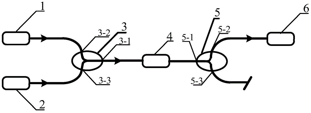
[0026] like figure 1 As shown, this embodiment is an all-optical fluid mass flow monitoring device, including a heating light source 1, a detection light source 2, a first filtering wavelength division multiplexer 3, a sensing unit 4, and a second filtering wavelength division multiplexer. Apparatus 5 and spectral analysis equipment 6. The heating light source 1, the detection light source 2, and the sensing unit 4 are all connected to the first filtering wavelength division multiplexer 3, respectively, and the second filtering wavelength division multiplexer 5 is respectively connected to the other end of the sensing unit 4 and the spectral analysis equipment. 6.

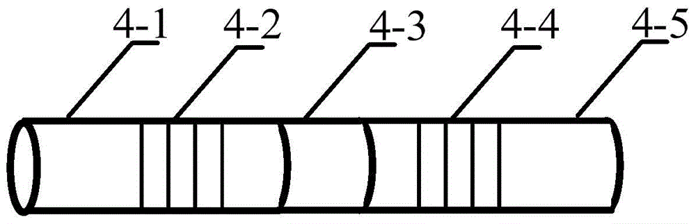
[0027] The structure of the sensing unit in this embodiment is as follows figure 2 As shown, the sensing unit 4 is a composite structure of a single-mode optical fiber (4-1), a photothermal optical fiber (4-3), and a single-mode optical fiber (4-5), which are spliced ​​by a fusion splicer. Fiber Bragg gratings ...

Embodiment 2

[0035] Other structures of this embodiment are the same as those of Embodiment 1 except the following features:

[0036] In this embodiment, for high-risk gases such as gas, carbon monoxide and acetylene, or corrosive gases such as chlorine and hydrogen chloride, the length of the fiber Bragg gratings 4-2 and 4-4 is selected as 2mm, and the length of the photothermal fiber 4-3 is selected as 1mm.

Embodiment 3

[0038] Other structures of this embodiment are the same as those of Embodiment 1 except the following features:

[0039] In this embodiment, for flammable and explosive liquids such as ethanol and isoacetone, the length of the fiber Bragg gratings 4-2 and 4-4 is selected as 2 mm, and the length of the photothermal fiber 4-3 is selected as 1 mm.


PUM


Abstract

The invention discloses an all-optical fluid mass-flow monitoring device and method. The device comprises a heating light source, a detecting light source, a first filter wavelength division multiplexer, a sensing unit and a spectral analytic apparatus. The sensing unit is in a composite structure of a single mode fiber, a photo-thermal fiber and a single-mode fiber; both the single mode fibers are provided with fiber gratings by carving, forming a Fabry-Perot cavity; the photo-thermal fiber forms a resonator. The method includes the steps: after the photo-thermal fiber of the sensing unit absorbs light emitted by the heating light source, the temperature rises and stabilizes after rising to a preset value; fluid to be detected flows by the sensing unit and brings away heat, and effective cavity length of the Fabry-Perot cavity changes, resulting in drift of interference peaks; drift distances of the interference peaks are detected, and current mass-flow of the fluid is obtained by data calibration. The all-optical fluid mass-flow monitoring device and method has such advantages as accurateness, sensitiveness, all-optical property, small size and safeness and is especially applicable to monitoring of flammable explosive fluids.

Description

technical field [0001] The invention relates to the research field of fluid mass flow monitoring, in particular to an all-optical fluid mass flow monitoring device and method. Background technique [0002] At present, fluid mass flow monitoring technology is widely used in various fields such as industrial production, energy measurement, environmental protection engineering and transportation. This monitoring technology can be used for both fluid mass flow measurement and process control. Thermal mass flowmeters are widely used in the market. The sensors in this flowmeter are composed of thermistors. When monitoring, the sensing unit is heated by an electrical method. Therefore, there is a potential safety hazard of electric sparks in the monitoring process, and the heating wire is also vulnerable to corrosion. In the environment where there are flammable and explosive liquids such as gasoline, kerosene, liquefied petroleum gas, etc., as well as high-risk gases such as gas...

Claims


Application Information

Patent Timeline
Patent Type & Authority Applications(China)
IPC IPC(8): G01F1/76
CPCG01F1/68G01F1/76
Inventor 周斌姜恒和何赛灵陈卓高少锐
Owner SOUTH CHINA NORMAL UNIVERSITY
Why Eureka
Try Eureka