A virtual instrument-based DC inductance testing system and method

A technology of DC inductors and virtual instruments, which is applied in the direction of instruments, measuring devices, and measuring electrical variables, etc. It can solve problems such as the inability to reproduce the working environment of DC inductors, the low degree of automation, and the inability to accurately measure parameters, so as to reduce the interval time , Easy to adjust quickly and ensure the effect of charging speed

Inactive Publication Date: 2017-05-24
BEIFANG UNIV OF NATITIES
View PDF4 Cites 0 Cited by
  • Summary
  • Abstract
  • Description
  • Claims
  • Application Information

AI Technical Summary

Problems solved by technology

The oscilloscope method is "a method for measuring inductance based on a half-bridge circuit" proposed in "Power Electronics Technology" 2008, 42(7): 40-42. This method can provide excitation current conditions similar to the actual working conditions of the inductor, and It can fully reflect the dynamic magnetization characteristics of the inductor and obtain more reference value inductance values. However, this method uses an oscilloscope to test the current and voltage waveforms of the charging and discharging of the inductor to be tested, and then performs data processing to obtain the intuition curve. It is inseparable from expensive High-bandwidth digital oscilloscope, and the degree of automation is not high. This method is also a method of estimation and intuition commonly used by customers for large DC inductance or power inductance manufacturers. It is relatively primitive
In the prior art, there is no feasible virtual instrument system and test method for DC inductors. Since none of them can reproduce the working environment of DC inductors, they cannot accurately measure their corresponding parameters, and each has its own inability Weaknesses and drawbacks to overcome

Method used


Image

  • A virtual instrument-based DC inductance testing system and method
  • A virtual instrument-based DC inductance testing system and method
  • A virtual instrument-based DC inductance testing system and method

Examples


Embodiment Construction

[0050] The present invention will be further described in detail below in conjunction with specific embodiments, which are explanations of the present invention rather than limitations.

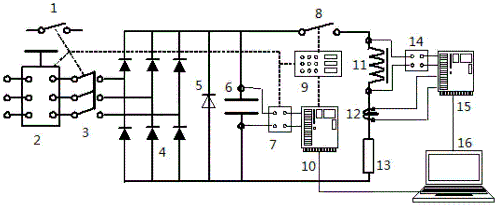
[0051] Specifically, such as image 3 As shown, the test system of the present invention includes four parts: a charging circuit, a discharging circuit, a data acquisition circuit and a control board 9 .

[0052] Among them, such as image 3 As shown, the charging part completes the charging of the capacitor bank 6 to realize the function of charging the voltage to the rated voltage of the DC inductor 11 to be tested, which includes a relay 1, a three-phase AC voltage regulator 2, an AC contactor 3, and a three-phase rectifier Bridge 4 and capacitor group 6; Adopt the relay 1 of 24V, 20mA in this optimal example; Capacity is the three-phase AC voltage regulator 2 of 6kVA, 1000V; The AC contactor 3 of 20A; The three-phase rectifier bridge 4 of 1000V, 200A; Including 24 capacitors with a with...


PUM


Abstract

The invention provides a system for testing a DC inductor based on a virtual instrument. The system comprises a control board card, a capacitor bank connected with the two ends of the DC inductor to be detected, a charging circuit for charging the capacitor bank according to the charging command signal of the control board card, a discharging circuit for enabling the capacitor bank to discharge to the DC inductor to be detected according to the discharging command signal of the control board card, and a data acquisition circuit; the data acquisition circuit comprises a low-speed acquisition card and a high-speed acquisition card, as well as a PC in connection communication with the two acquisition cards. The testing method comprises 1) initiating the testing system, 2) performing input setting on the parameters of the testing parameters, 3) acquiring the data of the DC inductor to be detected, 4) processing the set parameters and the acquisition data by use of Levenberg-Marquadt algorithm based on an LCR discharge time current function, thereby obtaining the nonlinear parameter estimated values f, g and h of the LCR discharge time current function, and 5) obtaining the DC inductance and the DC resistance of the DC inductor to be detected according to a formula.

Description

technical field [0001] The invention relates to the technical field of DC inductance testing, in particular to a virtual instrument-based DC inductance testing system and method. Background technique [0002] The so-called inductor refers to a common electronic device that forms a magnetic field induction in the coil after the air-core or iron-core coil passes the current, and the induced magnetic field will generate an induced current to resist the current passing through the coil. It is mainly used for voltage conversion, signal Coupling, resonance, electromagnetic induction and other circuits. According to whether the direction of current flow in the coil changes, it is divided into AC inductance and DC inductance. [0003] Traditional inductance measurement methods are mainly for AC inductance, which can be divided into voltammetry, LCR meter method and resonance method. Voltammetry can provide a wide range of AC and DC excitation amplitudes, but the optional frequency...

Claims


Application Information

Patent Timeline
Patent Type & Authority Patents(China)
IPC IPC(8): G01R27/26G06F9/455
Inventor 盛洪江
Owner BEIFANG UNIV OF NATITIES
Why Eureka
Try Eureka