
Continuous steam recompression evaporation system using flash steam waves

A vapor recompression and evaporation system technology, which is applied in multiple-effect evaporation, evaporator accessories, etc., can solve the problems of low ejector boosting efficiency, insufficient use of secondary steam latent heat, and insignificant energy-saving effect, etc. Achieve excellent performance with liquid, wide application range and small structure size

Active Publication Date: 2015-03-11
艾肯(江苏)工业技术有限公司
View PDF7 Cites 12 Cited by
  • Summary
  • Abstract
  • Description
  • Claims
  • Application Information

AI Technical Summary

Problems solved by technology

But the biggest problem is that the booster efficiency of the ejector is low, the latent heat of the secondary steam cannot be fully utilized, and the energy saving effect is not significant

Method used


Image

  • Continuous steam recompression evaporation system using flash steam waves
  • Continuous steam recompression evaporation system using flash steam waves

Examples


Embodiment 1

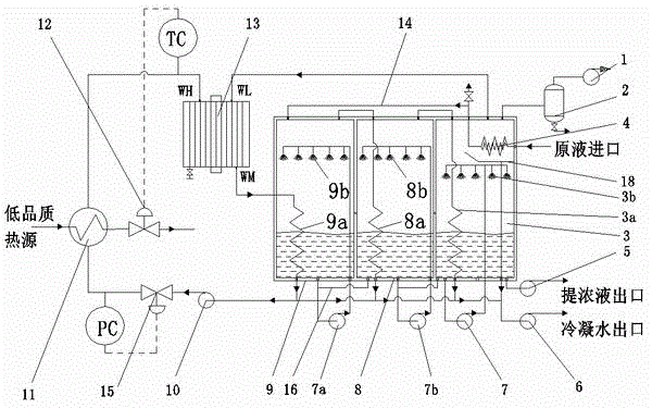
[0021] Example 1 Using saturated or superheated liquid water to complete the recompression of secondary steam in a flash wave supercharger.

[0022] figure 1 A flash wave vapor recompression continuous evaporation system is shown. In the figure, the flash wave vapor recompression continuous evaporation system includes a three-effect evaporator, concentrated liquid pump 5, condensate pump 6, heat source heat exchanger 11, and the three-effect evaporator consists of a first-effect evaporator 9 and a second-effect evaporator 8 Composed with the final effect evaporator 3, the bottom of the first effect evaporator 9 and the secondary effect evaporator 8, and the bottom of the secondary effect evaporator 8 and the final effect evaporator 3 are connected to each other by a communication pipe 16. The first effect circulation pump 7a of the first effect evaporator 9 is used to connect the first effect liquid uniform distributor 9b in the first effect evaporator 9, and the second effec...

Embodiment 2

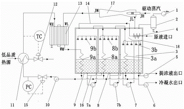
[0027] Example 2 Combined use of steam ejector and flash wave supercharger to complete the recompression of secondary steam.

[0028] figure 2 A continuous evaporation system combining thermal vapor recompression with flash wave vapor recompression is shown. figure 2 and figure 1 The difference is that the upper space of the final effect evaporator 3 is connected to the low-pressure steam inlet JL of the steam ejector 17 by a pipeline, and the boost outlet JM of the steam ejector 17 is connected to the low-pressure steam inlet WL of the flash wave supercharger 13 , driving steam to enter from the high-pressure inlet JH of the steam injector 17.

[0029] In each effect evaporator, the heat exchange on the evaporating side adopts a forced circulation liquid distributor to complete the liquid distribution. In the co-current and co-current feeding methods, the feed liquid of the front effect and the after effect is transported by the pressure difference; in the counter-curren...


PUM


Abstract

The invention discloses a continuous steam recompression evaporation system using flash steam waves, belongs to the technical field of hot-method evaporation. Specifically, a flash steam wave pressure booster is introduced, steam recompression is completed by using flash steam waves by using the pressure boosting characteristics of flash steam waves of saturated water with pressure, two combination systems of steam recompression by using flash steam waves and pressure boosting / steam thermal compression of the flash steam waves are achieved, tail-effect secondary steam is fed into a flash steam wave booster and is subjected to recompression, after the energy grade is increased, the tail-effect secondary steam is fed into a primary-effect evaporator to be used as a driving heat source, the generated secondary steam is separated in a gas-liquid separation module, and is further used as a lower-effect heat source for continuous evaporation, and a stock solution is pumped out of the device after being concentrated to be saturated in concentration in the evaporators. By adopting the continuous steam recompression evaporation system, the compression process that gas phase compression of steam is converted to liquid phase compression is achieved, the efficiency is remarkably improved, the difficulty that a steam compressor is hard to design and manufacture is solved, and the pressure boosting efficiency is relatively high when being compared with that of a steam ejector.

Description

technical field [0001] The invention relates to a flash vapor wave vapor recompression continuous evaporation system, which belongs to the technical field of thermal evaporation. Background technique [0002] The arbitrary discharge of high-salt wastewater has brought great pressure to the ecological environment, which has attracted widespread attention from the government and the public, and there is an urgent need for cost-effective high-salt wastewater treatment technology. Among the three mainstream desalination technologies today, the reverse osmosis membrane (RO) method is economical, but has problems such as membrane fouling and low production capacity; The energy consumption of the method is high (for example, the three-effect MED consumes about 0.4 tons of fresh steam / ton of wastewater), and the economy is poor. The industry even believes that the thermal method is not the development direction of the brine treatment technology. However, thermal treatment of saline...

Claims


Application Information

Patent Timeline
IPC IPC(8): B01D1/26B01D1/30
Inventor 代玉强胡大鹏张斯亮朱彻邹久朋陶盛洋程永航张大为
Owner 艾肯(江苏)工业技术有限公司
Learn More