

Waste recycling and regenerating device used in flue gas purification method
A flue gas purification and regeneration device technology, applied in chemical instruments and methods, separation methods, alkali metal compounds, etc., can solve problems such as high investment and operating costs, difficult operation, and complex processes, so as to save operating costs and avoid Dust leakage, small dosage effect
- Summary
- Abstract
- Description
- Claims
- Application Information
AI Technical Summary
Problems solved by technology
Method used
Image

Examples
Embodiment 1
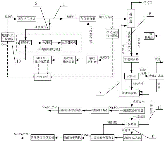
[0058] The present invention proposes a device for recovering and regenerating waste in the flue gas purification method, which mainly involves recovering SOx and NOx in the original flue gas to prepare Na 2 SO 4 、NaNO 3 In this example, the original flue gas is firstly processed by flue gas purification equipment to obtain purified gas. SOx and NOx in the original flue gas are captured into desulfurization and denitrification wastewater to form a certain concentration of sodium sulfate, Sodium nitrate mixed solution, that is: desulfurization and denitrification wastewater, and then the Na in the desulfurization and denitrification wastewater is passed through the wastewater regeneration system 2 SO 4 and NaNO 3 After separation, Na 2 SO 4 and NaNO 3 product. The device is easy to operate, not only can remove the pollutants in the original flue gas, reduce environmental pollution, but also obtain Na 2 SO 4 、NaNO 3 The product greatly reduces the cost of air pollutant...
Embodiment 2
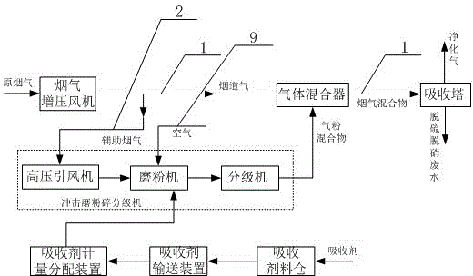
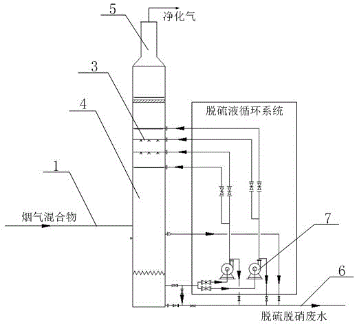
[0060] The difference between this embodiment and Example 1 is that the coarse flue gas purification involved in this embodiment is compared with the traditional flue gas purification method, the absorbent is metered and sent to the pulverizer system for crushing, and the pulverized absorbent particles are passed through The dry powder injector is sent into the main flue 1 to mix and react with the raw flue gas. In the traditional method, the purification efficiency of the absorbent to the raw flue gas is usually about 50%, and the desulfurization efficiency is low. In order to improve the absorbent work efficiency, the present embodiment proposes the following design: the original flue gas in the main flue is sent into the absorption tower 4 through the flue gas system, and the improvement of the flue gas system is that the flue gas system is mainly composed of the auxiliary flue 2 and the interconnected auxiliary flue The main flue is composed of 1. At the same time, an impac...
Embodiment 3
[0062] The difference between this embodiment and Embodiment 2 is that in this embodiment, after the original flue gas is split, the volume ratio of the flue gas passing through the main flue 1 and the auxiliary flue gas passing through the auxiliary flue 2 is 9: 1.
[0063] In the actual application process of this embodiment, the original flue gas is sent into the main flue 1 through the flue gas booster fan, and a part of the original flue gas enters the auxiliary flue 2 through the entrance of the auxiliary flue 2, which is called auxiliary flue gas. A part of the original flue gas remains in the main flue 1, which is called flue gas. The auxiliary flue gas drives the absorbent and enters the impact mill crushing classifier together. The absorbent is pretreated in the impact mill crushing classifier and combined with the auxiliary flue gas. reaction, the obtained gas-powder mixture is sent to the main flue 1 through the outlet of the auxiliary flue 2, and then mixed and re...
PUM
 Abstract
Description
Claims
Application Information