Drilling pressure pushing pressurizer

A pressure-on-drilling and pressure-relief hole technology, which is applied to drill pipes, drill pipes, earthwork drilling, etc., can solve the problems of difficult to control the drilling pressure, drill bit chipping, small drilling pressure, etc., and achieves convenient maintenance and installation, and reliable Effect of torque transmission and service life improvement

Active Publication Date: 2015-03-11
BC P INC CHINA NAT PETROLEUM CORP +2
View PDF8 Cites 18 Cited by
  • Summary
  • Abstract
  • Description
  • Claims
  • Application Information

AI Technical Summary

Problems solved by technology

It is difficult to precisely control the drilling pressure under the condition of downhole passing the pilot
Excessive drill pressure can easily lead to drill bit chipping, drill sticking, and even the flexible shaft of the universal joint to break
The drill pressure is too small, the drill bit is easy to wear, and the casing cannot be drilled
Excessive fluctuation and instability of the drill pressure will also cause uneven cutting of the drill bit, chipping, and make the drill bit invalid.
[0005] At present, the main problems of the technology related to the stability of the drilling pressure are: the drilling pressure is uncontrollable during the drilling process; the conventional key connection is used to transmit the torque, and the bearing capacity is poor; after the drilling is completed, the ground cannot judge the completion of the drilling

Method used


Image

  • Drilling pressure pushing pressurizer
  • Drilling pressure pushing pressurizer
  • Drilling pressure pushing pressurizer

Examples


Embodiment Construction

[0031] The above and other technical features and advantages of the present invention will be clearly and completely described below in conjunction with the accompanying drawings. Apparently, the described embodiments are only some of the embodiments of the present invention, not all of them.

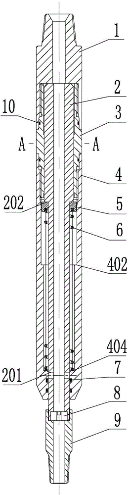
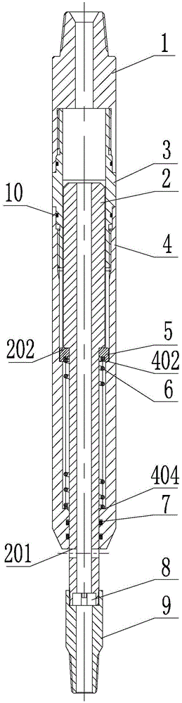
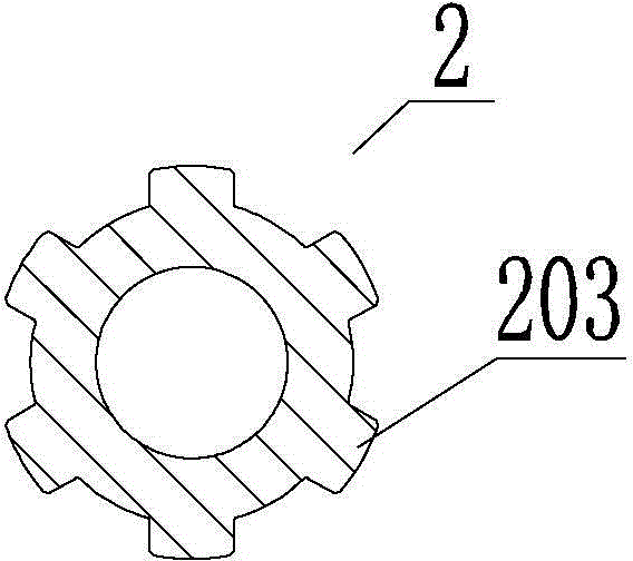
[0032] see figure 1 As shown, the drilling weight pusher of the present invention includes an upper joint 1, a piston 2, a housing 4, a throttle ring 8 and a lower joint 9. The shell 4 is a hollow cylinder, and one end of the shell 4 is connected with one end of the upper joint 1; The end of the piston 2 away from the upper joint 1 slides downwards out of the housing 4 , the protruding end of the piston 2 and the housing 4 are in sliding and sealing fit, and the protruding end of the piston 2 is connected with one end of the lower joint 9 .

[0033] The throttling ring 8 is connected with the protruding end of the piston 2 to generate throttling pressure difference. The upper joint 1,...


PUM


Abstract

The invention a drilling pressure pushing pressurizer which comprises an upper joint, a lower joint, a shell, a piston and a throttling ring, wherein the shell is a hollow barrel; one end of the shell is connected with one end of the upper joint; the piston is arranged in the inner cavity of the shell in a manner of moving up and down; one end, which is far away from the upper joint, of the piston extends out of the shell; the extending end of the piston is in sliding sealed fit with the shell and is connected with one end of the lower joint; the throttling ring is connected with the extending end of the piston and is used for generating throttling pressure difference; through holes are respectively formed in the upper joint, the piston, the throttling ring and the lower joint and are connected with one another in sequence to form a liquid guide channel; at least one pressure release hole penetrating from the through hole in the piston to the outer wall of the piston is formed in the lower part of the piston and retracts into or extends out of the shell along with the up-and-down sliding of the piston. The drilling pressure pushing pressurizer realizes drilling pressure adjustment and can judge the completion of hole drilling on the ground.

Description

technical field [0001] The invention relates to the technical field of oil and gas well casing drilling, in particular to a casing drilling technology suitable for radial and horizontal well operations in industries such as petroleum, coal, and natural gas. Background technique [0002] Water jet drilling radial horizontal well technology is a technology for drilling multi-branch radial wells in vertical wells, which can meet the needs of producing low-grade oil and gas reservoirs and increasing production of old wells, overcome the problem of low production of multiple wells faced by conventional vertical well development, and avoid using High costs brought about by large-scale production stimulation measures such as horizontal wells. [0003] In the process of drilling radial and horizontal wells with water jets, it is necessary to open windows on the casing first to prepare for the water jets to drill into the formation. The common method of casing window opening is dril...

Claims


Application Information

Patent Timeline
Patent Type & Authority Applications(China)
IPC IPC(8): E21B29/06
CPCE21B19/086
Inventor 胡强法盖志亮张友军于东兵张炎朱峰
Owner BC P INC CHINA NAT PETROLEUM CORP
Why Eureka
Try Eureka