Method for manufacturing metal microparticles
A technology of metal particles and manufacturing methods, applied in metal processing equipment, granulation in static tanks/troughs, granulation in rotating disks/pans, etc., can solve problems such as not being clear
- Summary
- Abstract
- Description
- Claims
- Application Information
AI Technical Summary
Problems solved by technology
Method used
Image

Examples
Embodiment
[0260] Examples are given below to describe the invention of the present application more specifically. However, the present invention is not limited to the following examples.
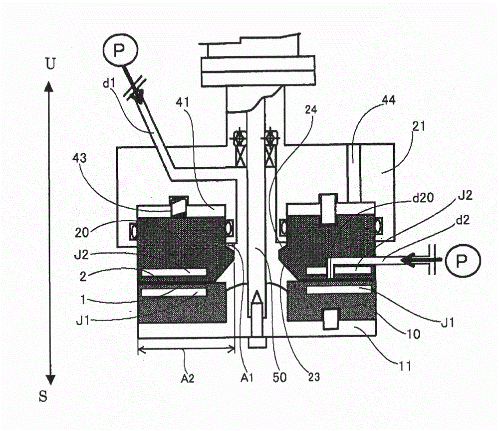
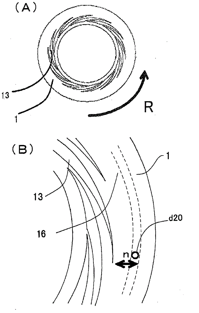
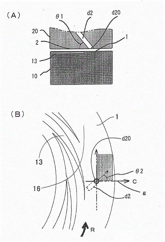
[0261] In the following examples, the so-called "from the center" is figure 1 The meaning of "from the first introduction part d1" in the processing device shown in , the first fluid refers to the above-mentioned first fluid to be processed introduced from the first introduction part d1, and the second fluid refers to the fluid from the first introduction part d1. figure 1 The above-mentioned second processed fluid introduced by the second introduction part d2 of the processing device shown in . In addition, as the opening d20 of the second introduction part d2, as figure 2 In (B), as shown by a dotted line, a concentric ring-shaped opening that wraps around the central opening of the processing surface 2 is used.
[0262] (A) Examples and comparative examples related to the production method of n...
Embodiment A1~A17
[0281] use figure 1The fluid treatment device shown in Table 3 mixed the nickel compound fluid with the formulation shown in Table 1 and the reducing agent fluid with the formulation shown in Table 2 under the treatment conditions in Table 3 to precipitate nickel particles. The obtained dry powder of nickel fine particles was analyzed. The results are shown in Table 4. It should be noted that the supply pressure of the first fluid and the rotational speed of the processing unit 10 are as described above. In addition, the nickel microparticle dispersion liquid discharged from between the processing surfaces 1 and 2 showed alkalinity in all of Examples A1 to A17.
[0282] As for the nickel compound fluid, in Examples A1 to A14, nickel sulfate hexahydrate was dissolved in a mixed solvent in which ethylene glycol, polyethylene glycol 600, and pure water were mixed. In order to change the pH and the sulfate ion concentration And add sulfuric acid, ammonium sulfate, potassium sul...
Embodiment A18~A23
[0297] Except that the recipe of the nickel compound fluid is shown in Table 5, and the treatment conditions are shown in Table 6, it was implemented similarly to the case of Examples A1 to A17 to obtain dry powder of nickel fine particles. The results are shown in Table 7. In addition, in all of Examples A15 to A23, the nickel microparticle dispersion liquid discharged from between the processing surfaces 1 and 2 showed alkalinity.
[0298] [table 5]
[0299]
[0300] [Table 6]
[0301]
[0302] [Table 7]
[0303]
[0304] It can be confirmed from Table 7 that by controlling the molar ratio (SO 4 2- / Ni), to suppress the particle size of the precipitated nickel particles from increasing, and at the same time promote the increase of the crystallite diameter. In addition, it was confirmed that the increase in the particle size was suppressed along with the increase in the crystallite diameter. Therefore, it was confirmed that the ratio (d / D) of the crystallite di...
PUM
| Property | Measurement | Unit |
|---|---|---|
| particle diameter | aaaaa | aaaaa |
| size | aaaaa | aaaaa |
| size | aaaaa | aaaaa |
Abstract
Description
Claims
Application Information
 - R&D
- Intellectual Property
- Life Sciences
- Materials
- Tech Scout
- Unparalleled Data Quality
- Higher Quality Content
- 60% Fewer Hallucinations
Browse by: Latest US Patents, China's latest patents, Technical Efficacy Thesaurus, Application Domain, Technology Topic, Popular Technical Reports.
© 2025 PatSnap. All rights reserved.Legal|Privacy policy|Modern Slavery Act Transparency Statement|Sitemap|About US| Contact US: help@patsnap.com