Novel flue gas denitrification device of CO waste heat boiler

A waste heat boiler and flue gas technology, applied in the field of flue gas denitrification, can solve the problems of low denitrification efficiency, not widely used, and high safety hazards, and achieve the effects of high denitrification efficiency, no secondary pollution, and reduced investment

Active Publication Date: 2015-03-18
北京美斯顿科技开发有限公司
View PDF2 Cites 7 Cited by
  • Summary
  • Abstract
  • Description
  • Claims
  • Application Information

AI Technical Summary

Problems solved by technology

[0004] The purpose of the present invention is to provide a new flue gas denitrification device for CO waste heat boiler, aiming to solve the problem of low denitrification efficiency of traditional liquid absorption method; high denitrification efficiency of adsorption method, but small adsorption amount, frequent regeneration, not widely used; high energy

Method used


Image

  • Novel flue gas denitrification device of CO waste heat boiler

Examples


Embodiment Construction

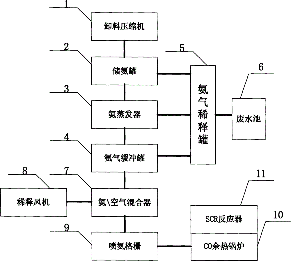
[0021] combined with figure 1 The present invention is described, the present invention is achieved in this way, a novel CO waste heat boiler flue gas denitrification device, the device includes a discharge compressor, ammonia storage tank, ammonia evaporator, ammonia buffer tank, ammonia dilution tank , waste water tank, ammonia\air mixer, dilution fan, ammonia injection grid, CO waste heat boiler, SCR reactor:

[0022] The unloading compressor unloads and compresses the liquefied ammonia transported by trucks;

[0023] The ammonia storage tank is located under the unloading compressor for storing liquid ammonia;

[0024] The ammonia evaporator is connected to the ammonia storage tank through pipelines to vaporize liquid ammonia;

[0025] The ammonia buffer tank is connected to the ammonia evaporator through pipelines, which is used to reduce the speed of ammonia gas and make the ammonia gas more gentle;

[0026] The inlet of the ammonia dilution tank is connected to the a...


PUM

PropertyMeasurementUnit
Apertureaaaaaaaaaa

Abstract

The invention discloses a novel flue gas denitrification device of a CO waste heat boiler. A discharged material concentrator is used for discharging and compressing liquid ammonia transported by a truck; an ammonia storing tank is positioned below the discharged material concentrator; an ammonia evaporator is connected with the ammonia storing tank by virtue of a pipeline; an ammonia gas buffering tank is connected with the ammonia evaporator by virtue of a pipeline; an inlet of an ammonia gas diluting tank is connected with the ammonia storing tank, the ammonia gas buffering tank and the ammonia evaporator; an ammonia/air mixer is positioned below the ammonia gas buffering tank and connected with an ammonia spraying grid; the CO waste heat boiler is connected with the ammonia spraying grid by virtue of a pipeline; an SCR reactor is positioned above the CO waste heat boiler and communicated with the CO waste heat boiler. According to the novel flue gas denitrification device, the SCR reactor is firstly combined with the waste heat boiler for denitrifying of an FCCU; an SCR catalytic reactor module is directly placed at the upper layer of the waste heat boiler, so that the whole SCR reactor is compact in arrangement, the occupation area is reduced, and the investment is lowered; the denitrifying efficiency is high, the technical maturity is high, the utilization rate of a reducing agent is high, oxygen in waste gas rarely involves in a reaction, the heat release is small, and no side products and no secondary pollution are caused.

Description

technical field [0001] The invention belongs to the field of flue gas denitrification, and in particular relates to a novel flue gas denitrification device for a CO waste heat boiler. Background technique [0002] As NOx emissions continue to grow. National policies, national standards, and local standards related to NOx emission limits for flue gas from catalytic cracking units in China are becoming increasingly stringent. FCC flue gas denitrification will soon be included in mandatory implementation specifications. The main source of NOx in catalytic cracking flue gas is catalytic Nitrogen-containing compounds in raw materials, but so far there is no mathematical model for accurately predicting the relationship between nitrogen content in raw materials and NOx generation in flue gas. From the experience of FCCU operation, the amount of NOx in the flue gas is also related to the added carbon monoxide combustion aid and the heavy metal on the catalyst. The removal and trea...

Claims


Application Information

Patent Timeline
IPC IPC(8): B01D53/90B01D53/56
Inventor 王新元
Owner 北京美斯顿科技开发有限公司
Why Eureka
Try Eureka