Optimal waste heat utilization set for use at cold end of boiler of thermal power generating unit

A technology of thermal power units and boilers, applied in lighting and heating equipment, indirect carbon dioxide emission reduction, combustion methods, etc., can solve the problems of small power generation contribution of units, increase of heat transfer area, large loss of useful energy, etc., and achieve the reduction of exhaust gas temperature , Increase the air temperature and reduce energy consumption

Inactive Publication Date: 2015-03-18
JINAN HIPOWER TECH
View PDF0 Cites 0 Cited by
  • Summary
  • Abstract
  • Description
  • Claims
  • Application Information

AI Technical Summary

Problems solved by technology

However, there is a limit to reducing the exhaust gas temperature. On the one hand, when the exhaust gas temperature is relatively low, as the temperature of the flue gas further decreases, the temperature difference with the air decreases, that is, the heat transfer area of ​​the air preheater increases a lot, and the temperature of the flue gas decreases. On the other hand, when the exhaust gas temperature is low and the wall temperature of the preheater tube is lower than the dew point of the flue gas, low-temperature corrosion will occur, and the preheater will need to be replaced after one or two years of operation, and in severe cases, it will need to be replaced within half a year
Another way is to add a low-pressure economizer at the tail of the flue, appropriately increase the heating surface of the economizer, impose waste heat utilization of the flue gas, and increase the temperature of the feed water. The coal burner utilizes the waste heat of the flue gas, which contributes little to the power generation of the unit and has a great loss of useful energy

Method used


Image

  • Optimal waste heat utilization set for use at cold end of boiler of thermal power generating unit

Examples


Embodiment Construction

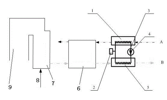
[0019] Accompanying drawing is a kind of specific embodiment of the present invention.

[0020] Thermal power unit boiler cold end optimized waste heat utilization device, after the air preheater 6, there are air-oil heat exchanger 1 and flue gas-oil heat exchanger 5, air-oil heat exchanger 1 and flue gas-oil heat exchanger The devices 5 are connected by a circulation pipeline 3, the circulation pipeline is filled with heat transfer medium and heat transfer oil, and the circulation pipeline is provided with an expansion tank 2 and a circulation pump 4; one end of the flue gas-oil heat exchanger 5 is preheated with the air One end of the air-oil heat exchanger 1 is connected to the air inlet of the air preheater, and the other end is provided with an air inlet A.

[0021] The shells of the air-oil heat exchanger 1 and the flue gas-oil heat exchanger 5 are provided with heat exchange tube bundles for accommodating heat-conducting oil. Air or flue gas runs outside the heat exchan...


PUM


Abstract

The invention discloses an optimal waste heat utilization set for use at the cold end of a boiler of a thermal power generating unit. An air-oil heat exchanger and a flue gas-oil heat exchanger are provided behind an air preheater; the air-oil heat exchanger is connected with the flue gas-oil heat exchanger through a circulating pipeline; the circulating pipeline is filled with heat transfer medium, heat transfer oil; the circulating pipeline is provided with an expansion tank and a circulating pump. One end of the flue gas-oil heat exchanger is connected with a flue gas outlet of the air preheater; the other end of the flue gas-oil heat exchanger is provided with another flue gas outlet. One end of the air-oil heat exchanger is connected with an air inlet of the air preheater; the other end of the air-oil heat exchanger is provided with another air inlet. The optimal waste heat utilization set has the advantages that smoke emission temperature can be greatly lowered, utilization of flue gas waste heat is achieved, load of the air preheater is reduced, thermal deformation and air leakage are reduced for the air preheater, and energy consumption of the thermal power generating unit is reduced.

Description

technical field [0001] The invention relates to an optimized waste heat utilization device at the cold end of a thermal power unit boiler, which belongs to a method and a device for utilizing boiler flue gas waste heat and reducing the exhaust gas temperature of a thermal power unit. Background technique [0002] In the boiler heat loss, the power plant exhaust heat loss accounts for a large proportion. For every 10~15°C reduction in exhaust gas temperature, the boiler efficiency can be increased by 1%. At present, the design exhaust gas temperature of large-scale units is generally 120~130°C. With the continuous improvement of flue gas desulfurization and denitrification technology, the acid dew point of flue gas is around 90°C, so there is still a lot of room for the exhaust gas temperature to decrease. At the same time, the exhaust gas temperature of supercritical and ultra-supercritical unit boilers is generally higher than the design value, and the temperature of the f...

Claims


Application Information

Patent Timeline
Patent Type & Authority Applications(China)
IPC IPC(8): F23L15/00
CPCY02E20/34
Inventor 向文国王伟田鹏李硕
Owner JINAN HIPOWER TECH
Why Eureka
Try Eureka