A kind of vortex type graphene stripping device, graphene production system and production method

A technology of a peeling device and a production system, applied in the field of graphene production, can solve the problems of insufficient powder shear force, increase the amount of pressurized powder, and uneven pressure applied by graphite, achieve less structural defects and burrs, expand the application range, The effect of expanding the practical value

Active Publication Date: 2016-06-29
江苏碳谷二维世界科技有限公司
View PDF6 Cites 3 Cited by
  • Summary
  • Abstract
  • Description
  • Claims
  • Application Information

AI Technical Summary

Problems solved by technology

[0005] Among them, conventional grinding refers to grinding graphite in a mortar grinder. The disadvantages are: first, the shear force comes from the friction force caused by pressure, and the excessive pressure makes it difficult for the motor to drive the pestle body to rotate, which limits the shear force. If the pressure is too small, it is difficult to shear and peel off; secondly, the shearing efficiency is low, and increasing the amount of pressed powder will lead to insufficient shearing force of some powders; thirdly, the uneven pressure exerted by the pestle on the graphite is prone to overgrinding, and the Applying pressure to graphite will cause structural defects in graphene, and even shatter graphene after exfoliation, so that the obtained product has more "burrs" on the edges and small crystal size
[0010] During the research process, the inventors found that the main reason for the small size of the graphene obtained by the existing graphene peeling device is that the graphite is sheared in an unoriented direction, wherein the graphite layer is not parallel to the shear plane When it is sheared in the same way, the result tends to be that graphite is not sheared to exfoliate graphene, but graphite or graphene is crushed into smaller sizes

Method used


Image

  • A kind of vortex type graphene stripping device, graphene production system and production method
  • A kind of vortex type graphene stripping device, graphene production system and production method
  • A kind of vortex type graphene stripping device, graphene production system and production method

Examples


Embodiment 1

[0047] The invention relates to an eddy current graphene peeling device 1 and a graphene production system, and also relates to a graphene production method.

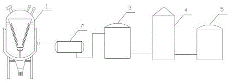
[0048] The graphene production system, such as figure 1 As shown, the vortex graphene peeling device 1, the storage tank 2, the centrifuge 3, the vacuum filtration device 4, and the freeze drying device 5 are included in sequence along the process sequence; the storage tank 2 is used to collect and stand the graphene peeling device 1 The product is discharged after processing, the centrifuge 3 is used to centrifuge the upper suspension in the storage tank 2 to separate exfoliated graphene and unexfoliated graphite, and the vacuum filtration device 4 is used to filter the supernatant obtained after the centrifuge 3 is centrifuged , Washing, freeze drying device 5 is used to dry the graphene after vacuum filtration. Here, the discharge port 112 of the vortex graphene peeling device 1 is connected with the feed port of the st...

Embodiment 2

[0056] One of the differences between this embodiment and Embodiment 1 lies in the structure of the shear blade 15 in the eddy current graphene peeling device 1.

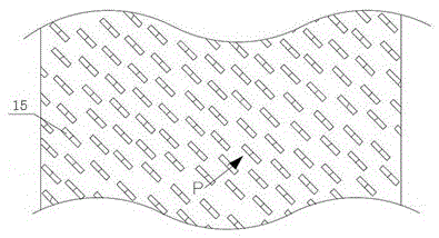
[0057] In this embodiment, in order to reduce the damage of the tooth tip of the shear blade 15 to the graphene structure, further reduce the defects of the produced graphene and increase the size of the graphene, such as Figure 4 with Figure 5 As shown, the cutting blade 15 is designed as a serrated hook knife: the end surfaces of each cutting blade 15 are perpendicular to the spiral line (P direction) where it is located, but the tooth tip of the cutting blade 15 is slightly facing away from the cutting The blade 15 is bent in the upward spiral direction to form the warped portion 150 of the hook knife. In the research, it is found that the angle α of the tooth tip of the shearing blade 15 slightly bent away from the spiral upward direction of the shearing blade 15 is 5-15°, which can maximize the balance between th...

Embodiment 3

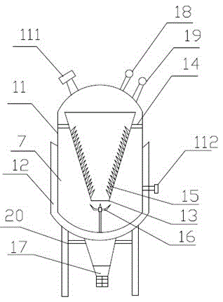
[0059] The difference between this embodiment and the second embodiment lies in the design of the feed port 111 and the configuration of the outer cylinder 11 in the vortex graphene peeling device 1. In this embodiment, such as Image 6 As shown, the feed port 111 is directly facing the outside of the inner cylinder 13, so that when it enters the outer cylinder 11 from the feed port 111, it is dispersed first and then enters the inner cylinder 13, which can avoid blockage of the groove between the shear blades 15 to a certain extent , And the graphite passes through the inner cylinder 13 in a manner parallel or approximately parallel to the inner wall of the inner cylinder 13.

[0060] At the same time, an ultrasonic vibration box 22 is provided in the outer cylinder 11 close to the feeding port 111, and is connected to the ultrasonic generator 21 outside the outer cylinder 11 through a wire. In this way, the graphite fed from the feeding port 111 can break the agglomeration in a...


PUM

PropertyMeasurementUnit
angleaaaaaaaaaa
angleaaaaaaaaaa

Abstract

A vortex graphene stripping device is disclosed. The vortex graphene stripping device comprises an outer cylinder provided with a heating jacket. The outer cylinder is provided with a pressure gage for detecting the pressure in the outer cylinder and a temperature measuring device for measuring the temperature in the outer cylinder. The top of the outer cylinder is provided with a feed port. The middle and lower part of the outer cylinder is provided with a discharging port. An inner sleeve of the outer cylinder is provided with a truncated cone-shaped inner cylinder with a downward taper angle. The upper and lower ends of the inner cylinder are open. The inner cylinder is fixed in the outer cylinder in a suspension manner through a hollowed-out support. Shear blades used for stripping graphene flakes are tightly arranged on the inner wall of the inner cylinder. A groove is formed between each adjacent shear blades. A turbine is disposed between the lower end of the inner cylinder and the lower end of the outer cylinder, and is driven to rotate by a driving mechanism disposed outside the outer cylinder. Turbine blades are perpendicular to and towards the opening at the lower end of the inner cylinder. The vortex graphene stripping device can achieve successful stripping of graphene. The invention also relates to a graphene producing system comprising the vortex graphene stripping device and a graphene producing method.

Description

Technical field [0001] The invention relates to the technical field of graphene production, in particular to a device for peeling off eddy current graphene and a graphene production system, and also to a graphene production method. Background technique [0002] Graphene is a sheet-like two-dimensional material, the carbon atoms in it are sp 2 The hybrid orbitals form a hexagonal honeycomb lattice structure. This special two-dimensional structure causes graphene to exhibit various special properties, such as high strength, high hardness, high thermal conductivity and electrical conductivity; due to these structural characteristics and performance characteristics, graphene is known as a protective coating The most promising potential materials such as layers, transparent bendable electronic components, and super-capacity capacitors. What needs to be added is that, strictly speaking, graphene is a single-layer sheet; however, due to the difficulty of preparing single-layer graphene...

Claims


Application Information

Patent Timeline
Patent Type & Authority Patents(China)
IPC IPC(8): C01B31/04
Inventor 戴加龙
Owner 江苏碳谷二维世界科技有限公司
Why Eureka
Try Eureka