Tunnel face cavity processing method for shield tunnel construction

A technology of shield tunneling and treatment method, applied in tunnels, tunnel linings, earthwork drilling and other directions, can solve the problems of ineffective treatment of tunnel face voids, poor grouting reinforcement effect, etc., to avoid long-term exposure, delicate The effect of high bonding and bonding strength

Active Publication Date: 2015-04-01
URBAN RAIL TRANSIT ENG CO LTD OF CHINA RAILWAY FIRST GRP CO LTD +1
View PDF6 Cites 9 Cited by
  • Summary
  • Abstract
  • Description
  • Claims
  • Application Information

AI Technical Summary

Problems solved by technology

[0004] The technical problem to be solved by the present invention is to provide a method for treating face voids in shield tunnel construction, which has simple steps, reasonable design, easy operation, low input cost, and good use effect in view of the above-mentioned deficiencies in the prior art. It can effectively solve the problems existing in traditional grouting reinforcement methods such as poor grouting reinforcement effect and inability to effectively deal with holes in the tunnel face.

Method used


Image

  • Tunnel face cavity processing method for shield tunnel construction
  • Tunnel face cavity processing method for shield tunnel construction
  • Tunnel face cavity processing method for shield tunnel construction

Examples


Embodiment 1

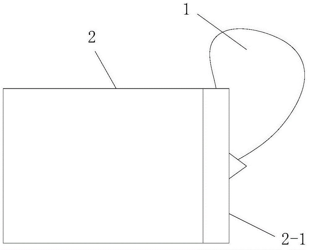
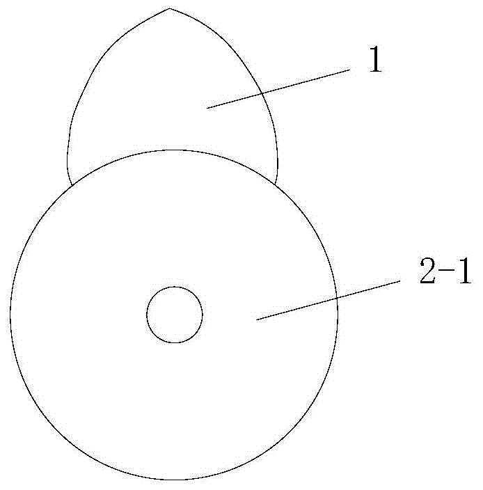
[0048] like figure 2 A method for treating tunnel face voids for shield tunnel construction is shown. The tunnel face voids to be processed are voids 1 located at the front and upper part of the cutter head 2-1 of the shield machine 2, including the following steps:

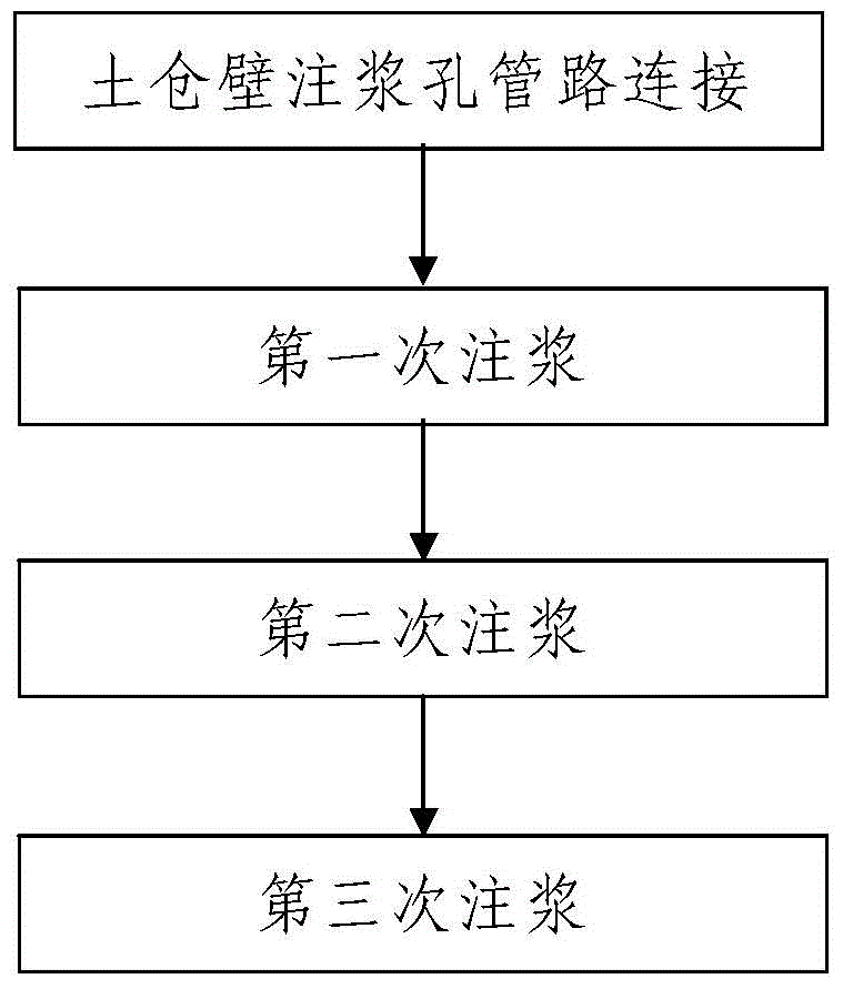
[0049] Step 1, the first grouting: the grouting system of the shield machine 2 is used, and the first cement mortar is injected into the lower part of the cavity 1 through the soil bin of the shield machine 2; during the first grouting process, the soil The internal pressure of the warehouse is controlled between 1.5bar and 3.5bar.

[0050] During the first grouting, inject the first grouting slurry into the soil bin from top to bottom; after the first grouting is completed, the inner upper part of the soil bin is filled with cement mortar, and the cement The bottom height of the mortar-filled section is lower than that of the cavity 1 .

[0051] The first grouting slurry is composed of cement, bentonite, fly ...

Embodiment 2

[0090] In this example, the difference from Example 1 is that the first grouting slurry described in step 1 is uniformly composed of cement, bentonite, fly ash, sand and water in a weight ratio of 48:52:195:580:410 Formed by mixing; the second cement mortar described in step 2 is formed by uniformly mixing cement, bentonite, fly ash, sand and water in a weight ratio of 95:78:235:580:470.

[0091] In this embodiment, the construction process of the remaining steps is the same as that of Embodiment 1.

Embodiment 3

[0093] In this example, the difference from Example 1 is that the first grouting slurry described in step 1 is uniformly composed of cement, bentonite, fly ash, sand and water in a weight ratio of 52:48:205:580:390 Formed by mixing; the second cement mortar described in step 2 is formed by uniformly mixing cement, bentonite, fly ash, sand and water in a weight ratio of 105:72:245:580:450.

[0094] In this embodiment, the construction process of the remaining steps is the same as that of Embodiment 1.


PUM


Abstract

The invention discloses a tunnel face cavity processing method for shield tunnel construction. The tunnel face cavity processing method for the shield tunnel construction includes steps that 1, primary grouting, to be specific, using a grouting system to fill first cement mortar to the lower part of the cavity from the top to bottom through a soil warehouse, wherein the first grouting size is composed of cement, bentonite, coal ash, sand and water according to the weight ratio of 45-55: 45-55: 180-220: 540-660: 360-440; 2, secondary grouting, to be specific, using the grouting system to fill second cement mortar to the middle of the cavity, wherein the second cement mortar is composed of cement, bentonite, coal ash, sand and water according to the weight ratio of 90-110: 68-82: 200-280: 540-660: 420-500; 3, tertiary grouting, to be specific, using the grouting system to fill cement slurry to the upper part of the cavity. The tunnel face cavity processing method for the shield tunnel construction is simple in steps, reasonable in design, easy and convenient to operate, low in invested cost, good in use effect and capable of solving the problems of a traditional grouting strengthening method.

Description

technical field [0001] The invention belongs to the technical field of shield tunnel construction, and in particular relates to a method for treating tunnel face voids for shield tunnel construction. Background technique [0002] The shield method is a fully mechanized construction method for modern tunnel construction, and the main mechanical equipment used is the shield machine 2. like Picture 1-1 , Figure 1-2 As shown, during the shield tunneling process, when the shield machine 2 is used for compressed air tool change operations, due to the long-term exposure of the tunnel face, the top of the tunnel face tends to collapse in large volume and form a cavity 1 . With the tool replacement of the shield machine, the exposure time of the cavity 1 on the top of the tunnel surface is longer, and the tunnel surface is unstable. Moreover, the cavity 1 will gradually develop over time, which will lead to the subsidence of the ground and affect the surrounding area. The safety ...

Claims


Application Information

Patent Timeline
Patent Type & Authority Applications(China)
IPC IPC(8): E21D9/06E21D11/10
CPCE21D9/08E21D11/10
Inventor 杨永强王江卡许建飞王俊英杨锦田黎明张大洋
Owner URBAN RAIL TRANSIT ENG CO LTD OF CHINA RAILWAY FIRST GRP CO LTD
Why Eureka
Try Eureka