
Direct drive independent variable pitch tidal current energy electric generation hydraulic turbine

A technology of independent pitch change and tidal current energy, applied in ocean energy power generation, reaction engine, hydroelectric power generation, etc., can solve the problem of difficult adjustment of bevel gear and blade bevel gear gap, inaccurate blade pitch angle transformation, and large volume of impeller hub and other problems, to achieve the effect of improving the strength of the main shaft, compact structure, and reducing the volume of the unit

Inactive Publication Date: 2015-04-01
HARBIN ENG UNIV
View PDF8 Cites 15 Cited by
  • Summary
  • Abstract
  • Description
  • Claims
  • Application Information

AI Technical Summary

Problems solved by technology

This method has a simple structure, high reliability, and is easy to implement various controls. In a complex tidal energy change environment, the pitch device has high requirements for driving force and pitch angle. This form of pitch makes the blade propeller The distance angle transformation is not accurate, and the gap between the bevel gear and the vane bevel gear is not easy to adjust
Publication No. CN201410018223.0 proposes an independent pitch control system and drive device for wind turbines, using three pitch motors to drive three blades to achieve individual deflection control for each blade. It is suitable for pitch angle control of turbine blades in a complex tidal current environment, but due to the independent design of three pitch structures, the volume of the impeller hub increases, the weight increases, and the cantilever stiffness becomes weak when the unit is fixed
Secondly, the composition of the traditional tidal energy turbine results in a large unit with too long main shaft and low strength; since the turbine works underwater, it is very difficult to seal between its various parts

Method used


Image

  • Direct drive independent variable pitch tidal current energy electric generation hydraulic turbine
  • Direct drive independent variable pitch tidal current energy electric generation hydraulic turbine
  • Direct drive independent variable pitch tidal current energy electric generation hydraulic turbine

Examples


Embodiment Construction

[0013] The present invention will be further described in detail below in conjunction with the accompanying drawings and specific embodiments.

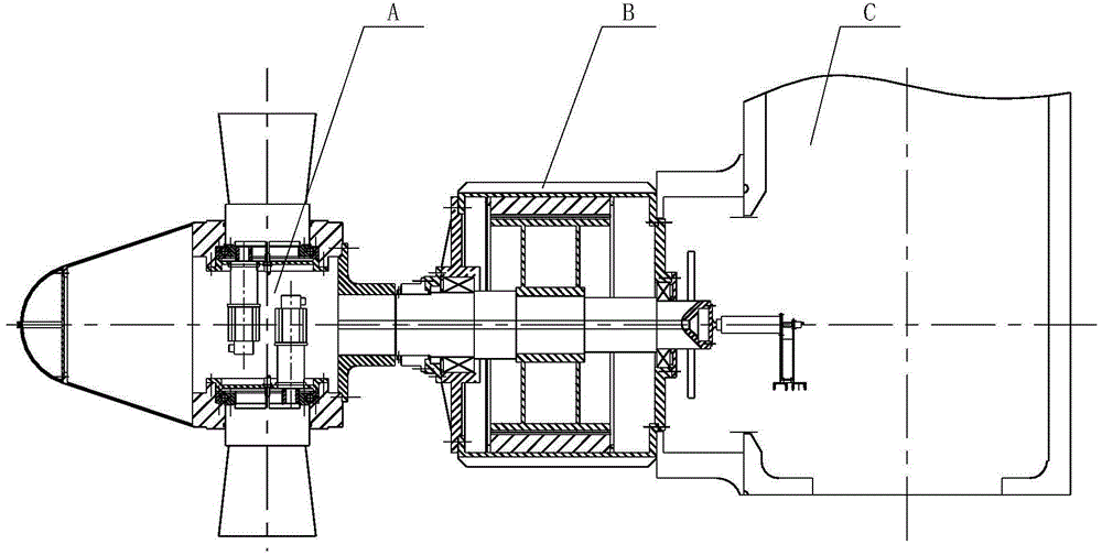
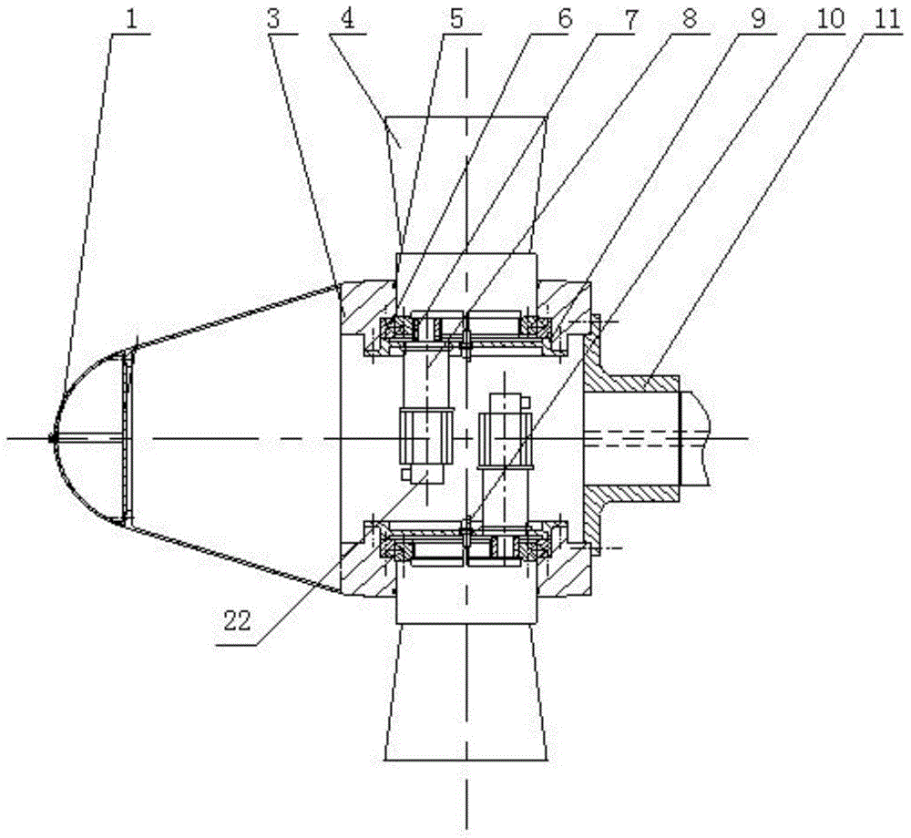
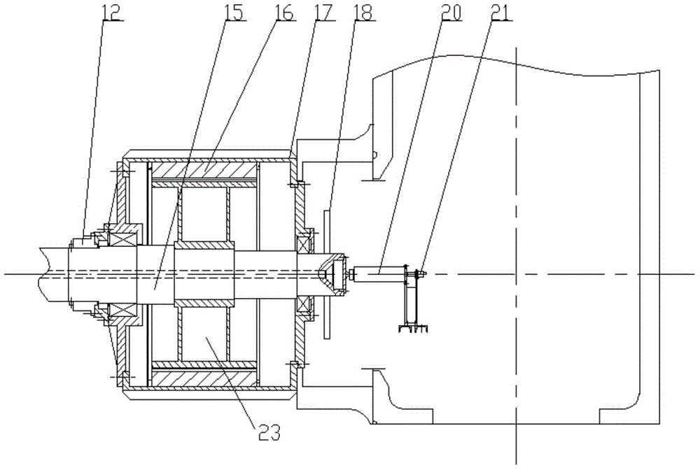
[0014] combine figure 1 , figure 2 and image 3 , the present invention includes an impeller A, a generator B and a tower C, specifically a fairing 1, a hub 3 fixedly connected to the fairing 1, blades 4 evenly arranged on the hub 3, and a flange 11 connected to the The generator B fixedly connected to the hub 3 and the tower C fixedly connected to the generator B also include an internal gear bearing 6, the bottom end of the root of the blade 4 is fixedly connected to the inner ring of the internal gear bearing 6, and the internal gear The outer ring of the type bearing 6 is fixedly connected with the wheel hub 3, the lower end of the internal gear bearing 6 is fixedly connected to the chassis 9, the lower end of the chassis 9 is equipped with a pitch motor 8, the lower end of the pitch motor 8 is provided with a pitch motor encod...


PUM


Abstract

The invention provides a direct drive independent variable pitch tidal current energy electric generation hydraulic turbine. The direct drive independent variable pitch tidal current energy electric generation hydraulic turbine comprises a fairing, a wheel hub, blades uniformly arranged on the wheel hub, an electric generator and a tower. The bottoms of the bases of the blades are fixedly connected to the inner circle of an inner-tooth bearing. The outer circle of the inner-tooth bearing is fixedly connected to the wheel hub. The lower end of the inner-tooth bearing is fixedly connected to a base plate. Variable pitch motors are mounted at the lower end of the base plate. The lower end of every variable pitch motor is provided with a variable pitch motor encoder. An output shaft of every variable pitch motor penetrates through a mounting hole in the base plate and provided with a pinion in a sleeving mode. The pinion is meshed with the inner circle of the inner-tooth bearing. The middle portions of the bases of the blades are provided with blade encoders. The blade encoders are connected to the variable pitch motor encoder through wires and control circuits. The direct drive independent variable pitch tidal current energy electric generation hydraulic turbine is compact in structure, small in size and capable of timely and accurately making appropriate changes for the complex water flow direction through the design that every motor independently controls the angle of the variable pitch of every blade.

Description

technical field [0001] The invention relates to a tidal current energy generating water turbine, in particular to a direct-drive independent pitch variable tidal current energy generating hydraulic turbine. Background technique [0002] The tidal current power generation turbine is a device that uses the kinetic energy generated by the flow of seawater to drive the impeller (including blades and hub) of the unit to rotate to generate electrical energy. The research on tidal current power generation turbines in various countries began in the early 21st century. The working principle of this equipment is very similar to that of traditional wind turbines. Since the average density of seawater is about 800 times that of air, the overall size of the tidal current power generation hydro turbine unit is much smaller than that of the wind power generation unit under the condition of the same power level of the two units. [0003] Usually, the tidal current power generation turbine ...

Claims


Application Information

Patent Timeline
Patent Type & Authority Applications(China)
IPC IPC(8): F03B13/26F03B3/14F03B15/06
CPCY02E10/20Y02E10/30
Inventor 孔凡凯张娣宗涛张亮耿敬朱永伟李振宇史宫男吴扬帆
Owner HARBIN ENG UNIV
Learn More