Intermediate frequency furnace, application thereof, and method for smelting silicon iron by utilizing crystalline silicon scraps

An intermediate frequency furnace and crystalline silicon technology, applied in the field of crystalline silicon waste treatment, to reduce energy consumption, solve the problem of landfill pollution, and achieve the effect of high purity

Inactive Publication Date: 2015-04-01
王先玉
View PDF11 Cites 8 Cited by
  • Summary
  • Abstract
  • Description
  • Claims
  • Application Information

AI Technical Summary

Problems solved by technology

[0018] Aiming at the existing problem of lacking a reasonable method for processing crystalline silicon cutting waste that can not only solve the problem of crystalline silicon waste, but also give full play to its own maximum characteristics, the present invention provides an intermediate frequency furnace and its application and utilization of crystalline silicon waste for smelting The ferrosilicon method not only solves the problem of crystalline silicon waste disposal, but also maximizes the value of crystalline silicon waste

Method used


Image

  • Intermediate frequency furnace, application thereof, and method for smelting silicon iron by utilizing crystalline silicon scraps
  • Intermediate frequency furnace, application thereof, and method for smelting silicon iron by utilizing crystalline silicon scraps
  • Intermediate frequency furnace, application thereof, and method for smelting silicon iron by utilizing crystalline silicon scraps

Examples


Embodiment 1

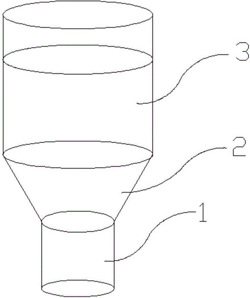
[0088] Such as figure 2As shown, an intermediate frequency furnace includes a furnace body, and the furnace body is divided into three sections: the lower section 1 of the furnace body, the middle section 2 of the furnace body, and the upper section 3 of the furnace body from bottom to top; the diameter of the lower section 1 of the furnace body is 764 mm, and the height is 700 mm. The shape of the longitudinal section of the middle section 2 of the furnace body is an internally hollow rounded table shape, and the diameter of the lower end of the middle section 2 of the furnace body is equal to the diameter of the lower section 1 of the furnace body; the height of the middle section 2 of the furnace body is 700mm, and the angle between the side surface and the horizontal plane is 60° , the height of the upper section 3 of the furnace body is 1462mm, and the diameter of the upper end of the middle section 2 of the furnace body is equal to the diameter of the upper section 3 of ...

Embodiment 2

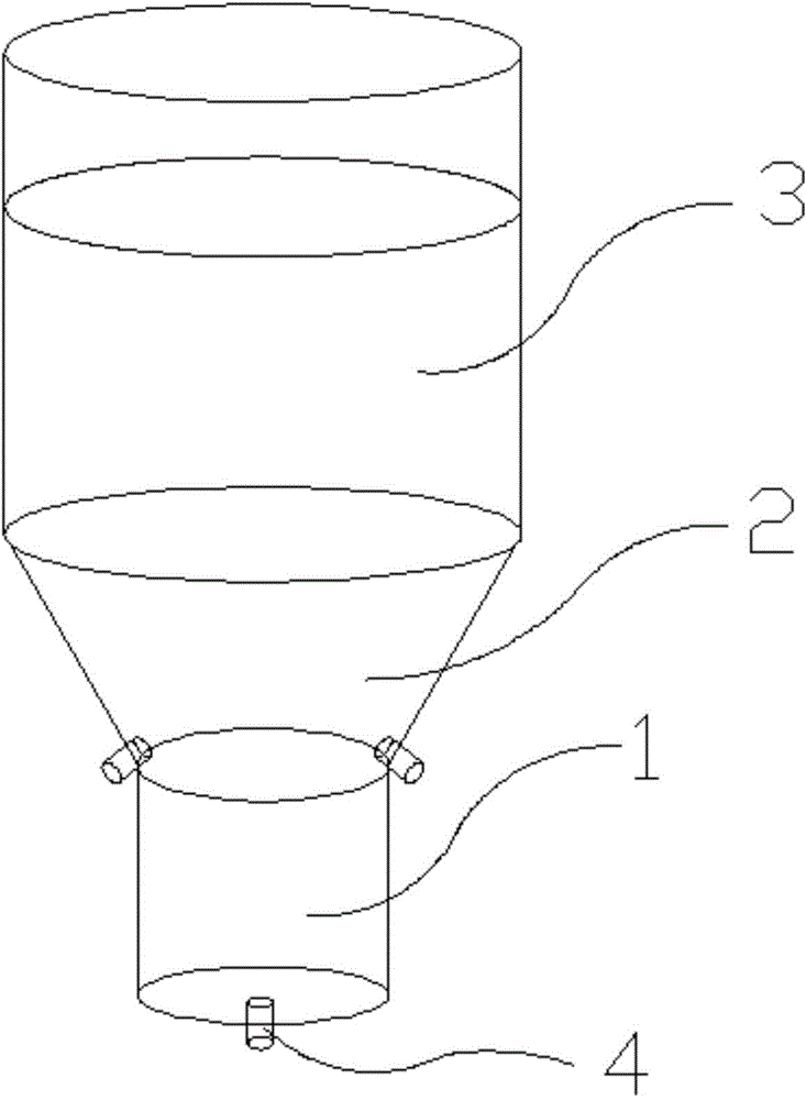
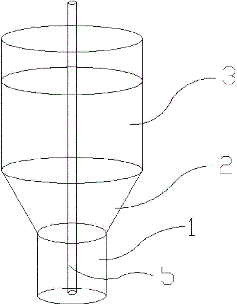
[0096] Such as image 3 As shown, an intermediate frequency furnace is the same as Example 1, the difference is that the height of the lower section 1 of the furnace body is 600mm, and the volume of the lower section 1 of the furnace body accounts for 40% of the working section of the furnace body; it also includes a blowing gun 5, and the feed passes through The spray gun 5 is inserted downwards into the bottom of the lower section 1 of the furnace body through the top of the furnace body. Silicon powder waste is added using a blow gun 5 .

[0097] (A) 2500kg of low-carbon scrap steel required for smelting ferrosilicon alloy is loaded into the furnace, the heating coils in the lower section 1 of the furnace body and the middle section 2 of the furnace body are energized to melt the scrap steel into molten iron, and continue to heat the molten iron to within the range of 1590°C to 1630°C; The composition of silicon powder waste is: Si: 72%, Si-C: 16%, Fe: 2%, and the rest is ...

Embodiment 3

[0103] Such as figure 2 As shown, an intermediate frequency furnace includes a furnace body, and the furnace body is divided into three sections: the lower section 1 of the furnace body, the middle section 2 of the furnace body, and the upper section 3 of the furnace body from bottom to top; the diameter of the lower section 1 of the furnace body is 874 mm, and the height is 800 mm. The shape of the longitudinal section of the middle section 2 of the furnace body is an internally hollow rounded table shape, and the diameter of the lower end of the middle section 2 of the furnace body is equal to the diameter of the lower section 1 of the furnace body; the height of the middle section 2 of the furnace body is 700mm, and the angle between the side surface and the horizontal plane is 60° , the height of the upper section 3 of the furnace body is 2024mm, the diameter of the upper end of the middle section 2 of the furnace body is equal to the diameter of the upper section 3 of the...


PUM

PropertyMeasurementUnit
particle sizeaaaaaaaaaa
melting pointaaaaaaaaaa

Abstract

The invention discloses an intermediate frequency furnace, application thereof, and a method for smelting silicon iron by utilizing crystalline silicon scraps, which belong to the field of crystalline silicon scraps disposal. The intermediate frequency furnace comprises a furnace body, wherein the furnace body is divided into a furnace body lower section, a furnace body middle section and a furnace body upper section from bottom to top; the diameter of the furnace body lower section is smaller than the diameter of the furnace body upper section; the shape of the longitudinal section of the furnace body middle section is in an inverted truncated cone shape with a hollow interior; the diameter of the lower end of the furnace body middle section is equal to the diameter of the furnace body lower section; the diameter of the upper end of the furnace body middle section is equal to the diameter of the furnace body upper section. The method for smelting the silicon iron by utilizing the crystalline silicon scraps comprises the following steps of charging steel scraps required for smelting the silicon iron alloy into the furnace, blowing silicon powder scraps into the furnace, finally discharging silicon iron alloy liquid, vacuum decarbonizing, casting cooling, and finishing the smelting process. According to the intermediate frequency furnace and the method, carbon elements in silicon carbide are utilized to reduce silicon dioxide, so that the energy consumption is reduced; in addition, carbon coke does not need to be added, so that the impact of element phosphorus and element sulphur is reduced; the product silicon iron is low-phosphorus low-sulphur low-carbon silicon iron, which has high value.

Description

technical field [0001] The invention belongs to the field of crystalline silicon waste treatment, in particular, it relates to an intermediate frequency furnace and its application and a method for smelting ferrosilicon by using crystalline silicon waste, more specifically, it relates to a special shaped intermediate frequency furnace and the use of solar panels A method of smelting ferrosilicon from crystalline silicon waste generated in the production process. Background technique [0002] At present, with the development of clean energy, solar technology is developing rapidly. In the process of producing solar panels, a large amount of crystalline silicon is used. A silicon chip with a diameter of 75mm can integrate tens of thousands to hundreds of thousands or even millions of components, forming microelectronics, and thus microcomputers, Microprocessor, etc. Due to current developments in information engineering, silicon is mainly used in microelectronics. In order t...

Claims


Application Information

Patent Timeline
Patent Type & Authority Applications(China)
IPC IPC(8): F27B14/06C22C33/04
CPCC22C33/04C22C35/005
Inventor 王先玉
Owner 王先玉
Why Eureka
Try Eureka