
Motion compensation method and system in three-dimensional imaging of dynamic object

A technology of motion compensation and three-dimensional imaging, applied in the field of motion compensation, can solve problems such as projection speed limitation, imaging error, and difficulty in limiting motion speed

Active Publication Date: 2015-04-01
SHENZHEN UNIV
View PDF8 Cites 16 Cited by
  • Summary
  • Abstract
  • Description
  • Claims
  • Application Information

AI Technical Summary

Problems solved by technology

But there are two problems: on the one hand, most of the current projection systems use digital projectors as projection devices, and their projection speed is greatly limited, which can only meet the imaging conditions of low-speed surface motion; on the other hand, projection The acquisition speed cannot be infinitely improved, and the dynamic surface is in a state of free movement, so it is difficult to limit its movement speed
Limited by the bottleneck of projection and acquisition speed, the impact of motion error will bring large errors to imaging when the surface motion speed is high

Method used


Image

  • Motion compensation method and system in three-dimensional imaging of dynamic object
  • Motion compensation method and system in three-dimensional imaging of dynamic object
  • Motion compensation method and system in three-dimensional imaging of dynamic object

Examples


Embodiment Construction

[0077] In order to make the object, technical solution and advantages of the present invention clearer, the present invention will be further described in detail below in conjunction with the accompanying drawings and embodiments.

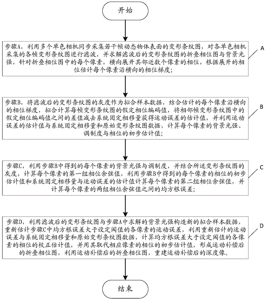
[0078] figure 1 A schematic flow chart of a motion compensation method in three-dimensional imaging of a dynamic object is shown, specifically including the following steps:

[0079] Step A, use multiple monochrome cameras to simultaneously collect several frames of deformed fringe images on the surface of a dynamic object, filter each frame of deformed fringe images collected by each monochrome camera, and solve the folded phase image and background of the filtered deformed fringe images For light intensity, for each pixel in the folded phase map, the phases of several adjacent pixels are horizontally expanded, and the phase gradient of each pixel along the horizontal direction is estimated according to the expanded phase.

[0080] It must be poi...


PUM


Abstract

The invention relates to a motion compensation method and system in three-dimensional imaging of a dynamic object. The motion compensation method comprises the following steps: firstly, carrying out primary estimation on a motion error; then, reestimating the motion error of each pixel of which the root-mean-square error is greater than a set threshold; calculating a correction estimation value of a phase of each pixel of which the root-mean-square error is greater than the set threshold according to the reestimated motion error and fixed phase drift and original deforming bar chart data of the system; replacing an initial estimation value of the phase of the corresponding pixel with the correction estimation value to form a wrapped phase diagram subjected to motion compensation; reestablishing a depth phase subjected to motion compensation by using the wrapped phase diagram subjected to motion compensation. The motion compensation method and system disclosed by the invention have relatively high reliability and relatively good compensation effect on the errors caused by motion, so that the dynamic surface measurement precision is greatly improved and the dynamic range of system measurement is expanded. The motion compensation method and system are applicable to a three-dimensional measurement system consisting of a projector and a single camera or two cameras, or motion error compensation of an absolute phase diagram subjected to phase unwrapping.

Description

technical field [0001] The invention belongs to the field of three-dimensional digital imaging, and in particular relates to a motion compensation method and system in three-dimensional imaging of dynamic objects. Background technique [0002] Dynamic surface imaging and measurement has a wide range of needs in the fields of assembly line inspection, military, experimental mechanics, and somatosensory games. At the same time, phase-assisted 3D imaging has the advantages of non-contact, fast speed, high precision, and high data density, and has been widely used in reverse engineering, quality control, defect detection, and cultural entertainment. Dynamic surface imaging using phase-assisted means can significantly improve imaging accuracy and resolution. The use of phase shift algorithm to solve the phase encoding requires that the phase encoding of the object cannot be changed during the acquisition process, but in the process of dynamic surface imaging, the target surface ...

Claims


Application Information

Patent Timeline
IPC IPC(8): G01B11/24G06T5/00
Inventor 彭翔关颖健殷永凯刘晓利
Owner SHENZHEN UNIV
Learn More