
Liquid level sensor based on POF (plastic optical fiber) optical fiber macrobending

A liquid level sensor and optical fiber macrobend technology, applied in the field of sensors, can solve the problems of cost sensitivity, increased liquid viscosity, large volume, etc., and achieve the effects of simplified process difficulty, strong anti-pollution ability, and good robustness

Active Publication Date: 2015-04-01
ZHONGBEI UNIV
View PDF8 Cites 2 Cited by
  • Summary
  • Abstract
  • Description
  • Claims
  • Application Information

AI Technical Summary

Problems solved by technology

At present, although there are liquid level sensors based on various principles, including magnetostrictive, capacitive, ultrasonic, and optical fiber, there are still prominent contradictions between liquid level measurement technology and market demand. , there are two main reasons: First, although the petrochemical industry has a huge demand for sensors, it is more sensitive to cost, and it is difficult for expensive and complex designs to be widely used in these fields.
Second, the liquid level measurement environment in the chemical industry is complex, and some are flammable and explosive liquids, which pose a huge challenge to the safety and adaptability of existing sensors
But this kind of probe still has the following problems: 1. The structure is made of twisted pair and wire winding, which leads to an increase in the viscosity of the liquid and a large "first bath" error
2. The structure obtains the macrobending dark field coupling signal through coupling. Because the macrobending coupling efficiency is very low, the power of the dark field signal is weak, which limits its propagation distance in the optical fiber, so it cannot be applied to long-distance When transmitting sensor signals
3. Due to the dual-fiber coupling structure, the structure has a large volume (macro bending radius is greater than 7mm, otherwise there will be gaps between the fibers and the coupling efficiency will be reduced), which limits its use in narrow spaces

Method used


Image

  • Liquid level sensor based on POF (plastic optical fiber) optical fiber macrobending
  • Liquid level sensor based on POF (plastic optical fiber) optical fiber macrobending
  • Liquid level sensor based on POF (plastic optical fiber) optical fiber macrobending

Examples


Embodiment Construction

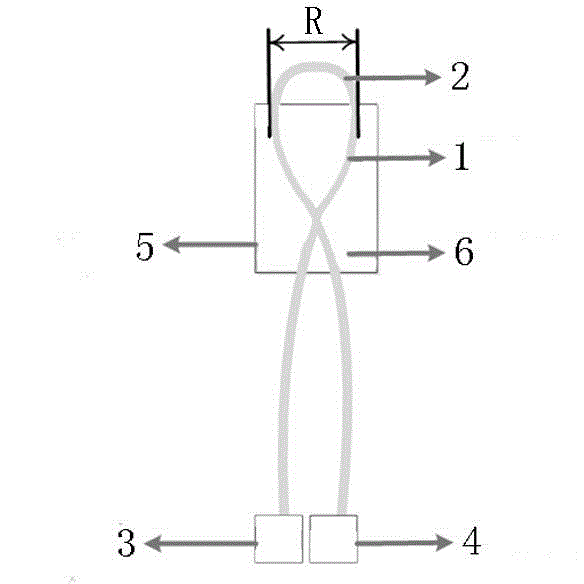
[0023] A POF bare fiber 1 (Mitsubishi, SK-40) is used to bend the top macrobend bending radius (R / 2) of 2.5mm single macrobend fiber ring structure, and the top macrobend part is used as the probe 2, and the POF bare fiber There are standard FC optical fiber connectors at both ends of the optical fiber, and the optical fiber connectors are respectively connected to the light source 3 and the power meter 4 in the test system. A standard FC optical fiber connector protective sleeve accessory is used as the fixed structure 5, and the single macrobend optical fiber ring structure is encapsulated in the fixed structure 5 with silica gel or epoxy resin 6, and the probe 2 is exposed from the top of the fixed structure 5. The outside of the POF bare optical fiber 1 other than the fixed structure 5 and the probe 2 is wrapped with a black heat-shrinkable sleeve. Its structure is as figure 1 shown.

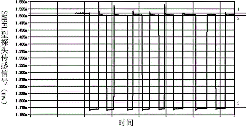
[0024] The fabricated SMBFL probe was subjected to a water immersion-outlet test. The...


PUM


Abstract

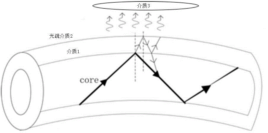
The invention relates to a liquid level sensor based on POF (plastic optical fiber) optical fiber macrobending. The liquid level sensor comprises a single macrobending optical fiber annular structure and a fixing structure, wherein the single macrobending optical fiber annular structure is manufactured through bending POF bare optical fiber and has the top macrobending radius being 2.5mm, the top macrobending part of the single macrobending optical fiber annular structure is used as a probe, two tail ends of the POF bare optical fiber are provided with optical fiber joints, the fixing structure is used for encapsulating the single macrobending optical fiber annular structure, and the probe is exposed out from the fixing structure. The liquid level sensor has the advantages that the design of the single macrobending optical fiber annular structure is adopted, the optical fiber macrobending is singly used for enhancing the CMFTIR (cladding mode frustratedtotal internal reflection) effect, the distinction degree being 1.06dB is realized, and the liquid level measurement requirement is met. In addition, the double optical fiber coupling is not needed, so that the process difficulty is simplified, the structure is more compact, and the liquid level sensor is suitable for being used in a narrow space. Meanwhile, the liquid viscosity of an SMBFL (single macro-bend fiber loop) structure is low, the initial bath error is greatly reduced, the SMBFL directly detects bright field signals with higher power, and the requirement of long-distance transmission is met.

Description

technical field [0001] The invention relates to a sensor, in particular to a liquid level sensor based on POF optical fiber macrobending. Background technique [0002] Liquid level measurement has a very wide range of application requirements and huge market space in the chemical, chemical, and petroleum fields. Various designs emerge in endlessly, from the simplest oil dipstick to liquid level sensors with complex structures. At present, although there are liquid level sensors based on various principles, including magnetostrictive, capacitive, ultrasonic, and optical fiber, there are still prominent contradictions between liquid level measurement technology and market demand. , There are two main reasons: First, although the petrochemical industry has a huge demand for sensors, it is more sensitive to cost, and it is difficult for expensive and complex designs to be widely used in these fields. Second, the liquid level measurement environment in the chemical industry ...

Claims


Application Information

Patent Timeline
Patent Type & Authority Applications(China)
IPC IPC(8): G01F23/00
Inventor 刘文怡侯钰龙张会新苏珊刘佳沈三民王红亮张彦军苏淑婧崔永俊甄成方熊继军刘俊
Owner ZHONGBEI UNIV
Learn More