Microwave frequency measurement chip as well as applying method and preparing method thereof

A microwave frequency measurement and chip technology, applied in frequency measurement devices and other directions, can solve the problems of large measurement error, high price, poor stability, etc.

Active Publication Date: 2015-04-01
UNITED MICROELECTRONICS CENT CO LTD
View PDF5 Cites 16 Cited by
  • Summary
  • Abstract
  • Description
  • Claims
  • Application Information

AI Technical Summary

Problems solved by technology

The currently reported schemes for microwave frequency measurement by photon means mainly include the following three schemes: one is to construct a function of unknown unknown frequency and time, the microwave signal modulates the optical carrier, and by measuring the two sidebands passing through a dispersive medium The unknown frequency is determined by the magnitude of the time delay difference generated later, but this method is limited by the instrument and the measurement error is large; the second is to construct a function of the unknown microwave frequency and space, and under small signal modulation, the optical sideband and optical The interval of the carrier wave in the frequency domain is converted into a spatial distribution, so as to detect the microwave frequency of the signal to be tested. Generally, chirped Bragg gratings, free-space diffraction gratings, and combinations of prisms are used.
The third is to construct the function of unknown microwave frequency and optical power intensity, filter the optical sidebands through optical comb filters or fiber gratings, and convert microwave frequency information into light intensity changes, which is also one of the main research directions at present. , the advantage of this scheme is that the low-speed photodetector can meet the needs, but there are also some problems such as limited frequency measurement range
In the current reports, the above three solutions are mostly based on discrete optical components, which are expensive and the test system is bulky and less stable.

Method used


Image

  • Microwave frequency measurement chip as well as applying method and preparing method thereof
  • Microwave frequency measurement chip as well as applying method and preparing method thereof
  • Microwave frequency measurement chip as well as applying method and preparing method thereof

Examples


Embodiment Construction

[0018] In order to make the objectives, technical solutions and advantages of the present invention clearer, the present invention will be further described in detail below with reference to the implementation examples. It should be understood that the specific embodiments described herein are only used to explain the present invention, but not to limit the present invention.

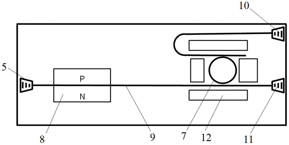
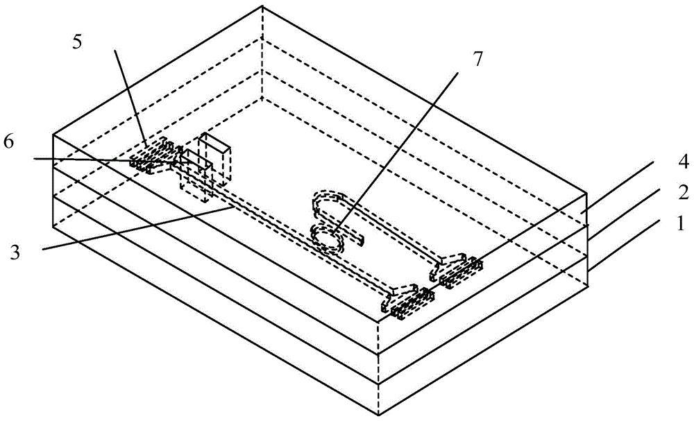
[0019] see figure 1 , the microwave frequency measurement chip of the present invention is based on silicon-based optoelectronic technology, including a grating coupler 5 , a phase modulator 8 , a filter based on a micro-ring resonant cavity 7 , and a bus waveguide 9 . The bus waveguide 9 is used to achieve signal transmission between the grating coupler 5 , the phase modulator 8 and the filter.

[0020] The grating coupler 5 is used for receiving the optical signal and outputting the optical carrier signal. The optical carrier signal is transmitted in the bus waveguide 9 , first through the phase mod...


PUM


Abstract

The invention discloses a microwave frequency measurement chip as well as an applying method and a preparing method thereof. The microwave frequency measurement chip comprises an optical grating coupler, a phase modulator, a filter based on a micro-ring resonant cavity and a bus waveguide. An optical signal is coupled by a coupling optical grating and enters the chip, an optical carrier signal is transmitted in the bus waveguide and first passes the phase modulator, the optical carrier signal is modulated by an unknown microwave signal to be measured through an intensity modulator, the modulated signal enters the micro-ring resonant cavity through the bus waveguide, two paths of optical power are respectively output at the upper and lower speech path ends of the filter, and the unknown microwave signal can be determined through calculating the specific value of the measured optical power. The microwave frequency measurement chip realizing the detection of the unknown microwave signal by a silicon-based photonic integrated chip has the advantages of small chip size, light weight, high integration, low cost and electromagnetic interference resistance. Meanwhile, the invention further discloses an applying method and a preparing method of the chip.

Description

technical field [0001] The invention relates to the field of plane optical waveguide integration, in particular to a microwave frequency measurement chip based on silicon-based optoelectronic technology, an application method and a manufacturing method thereof. Background technique [0002] In electronic information warfare, it is very important to quickly determine the frequency of intercepted radio frequency signals, which can be used for interception and eavesdropping of radar signals and communication signals, electronic countermeasures and countermeasures. With the development of millimeter wave technology and optoelectronic technology, the working frequency of modern electronic information warfare equipment has been continuously developed to a wider frequency band, and the content of electronic information warfare has also developed from the communication confrontation in the First World War to the Second World War. Radar countermeasures, navigation countermeasures and...

Claims


Application Information

Patent Timeline
Patent Type & Authority Applications(China)
IPC IPC(8): G01R23/02
Inventor 王皖君郭进冯俊波周杰崔乃迪
Owner UNITED MICROELECTRONICS CENT CO LTD
Why Eureka
Try Eureka