
Ultra-wideband receiver device based on microwave photonics and realizing method thereof

An ultra-wideband receiver and microwave photonics technology, applied in the field of microwave photonics, can solve the problems of inability to realize ultra-wideband signal reception, limited bandwidth and performance, and low conversion efficiency, so as to improve signal conversion efficiency and increase signal-to-noise ratio , the effect of improving stability

Inactive Publication Date: 2015-04-01
BEIHANG UNIV
View PDF4 Cites 24 Cited by
  • Summary
  • Abstract
  • Description
  • Claims
  • Application Information

AI Technical Summary

Problems solved by technology

This method cascades multiple modulators, resulting in low conversion efficiency and large insertion loss. At the same time, the frequency of the local oscillator signal required for receiving signals with a higher frequency is also higher, because the higher the frequency of the local oscillator signal, the worse the phase noise. As a result, the bandwidth and performance of the system are limited by the local oscillator signal
The second is a dual-arm Mach-Zehnder modulator plus a photoelectric oscillation circuit (see patent application number: 201310583404.3, "A Microwave Photonics Receiving Method"). The frequency bandwidth of this method is limited by the microwave devices in the photoelectric oscillation circuit, such as band-pass filtering. The bandwidth of the amplifier, low noise amplifier and phase shifter cannot achieve ultra-wideband signal reception

Method used


Image

  • Ultra-wideband receiver device based on microwave photonics and realizing method thereof
  • Ultra-wideband receiver device based on microwave photonics and realizing method thereof
  • Ultra-wideband receiver device based on microwave photonics and realizing method thereof

Examples


Embodiment Construction

[0031] Below in conjunction with accompanying drawing, the present invention will be further described:

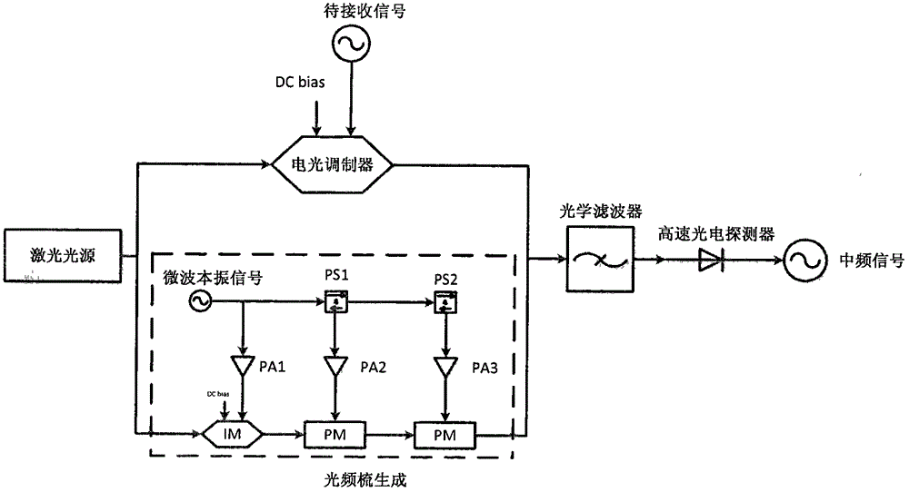
[0032] figure 1 It is a structural schematic diagram of the ultra-wideband receiver based on microwave photons of the present invention. The scheme consists of a laser light source, an electro-optical modulator, an optical frequency comb generation module, a single-mode fiber coupler, an adjustable optical filter, and a high-speed photodetector. The optical frequency comb generation module consists of a microwave local oscillator signal source, an intensity modulator ( IM), phase modulator (PM), microwave power amplifier (PA), and microwave phase shifter (PS).

[0033] The light source outputs laser light, and the single-mode fiber coupler divides the laser light into two beams according to the splitting ratio of 2:1 and enters the electro-optic modulator and the optical frequency comb generation module respectively; the electro-optic modulator modulates the microwave sig...


PUM

PropertyMeasurementUnit
Center wavelengthaaaaaaaaaa

Abstract

The invention discloses an ultra-wideband receiver device based on microwave photonics and a realizing method thereof. The realizing method comprises the following steps: dividing an optical signal output by a laser light source into two paths, wherein one path is used for generating an optical frequency comb with uniformly-spaced frequencies by adopting an external modulating mode, and the other path is used for modulating a to-be-received radio frequency signal through an electro-optical modulator and synthesizing the optical signal of the optical frequency comb; enabling the synthesized signal to pass through a tunable narrow bandpass filter for filtering out optical frequency carried with a to-be-detected signal and the fixed frequency point of the closest optical frequency comb, performing transformation through a high-speed detector, and obtaining difference frequency by realizing frequency beating and synthesizing of two frequencies, namely obtaining a frequency-converted medium-frequency signal under a to-be-measured signal. According to the ultra-wideband receiver device based on microwave photonics and the realizing method thereof, the optical frequency comb technology in microwave photonics is applied to designing microwave signal receiving; an adjustable optical fiber is combined to realize the ultra-wideband signal receiving and down-converting on the condition of a low-frequency intrinsic signal (2GHz-5GHz), wherein the receiving bandwidth is lower than that of the low-frequency intrinsic signal by dozens of times.

Description

technical field [0001] The invention relates to an ultra-wideband receiver device and a realization method, in particular to a microwave photon-based ultra-wideband receiver device and a realization method, and belongs to the technical field of microwave photonics. Background technique [0002] With the rapid development of information technology, the electromagnetic frequency band is fully utilized, the signal frequency band carrying various information covers a wide range, the signal parameters are changeable, and the signal form is becoming increasingly complex. The highly dense and complex signal environment requires electronic equipment receivers to have large receiving bandwidth, large dynamic range, high efficiency, high resolution, and the ability to receive and process multi-frequency and multi-form signals in a unified manner. With such a high demand, the traditional form of electronic signal receiver technology based on microwave devices has faced insurmountable b...

Claims


Application Information

Patent Timeline
IPC IPC(8): H04B10/67H04B1/7163
Inventor 白明方霄郑铮苗俊刚
Owner BEIHANG UNIV
Learn More