Battery heating structure built into motor driven system, and method thereof

A motor drive system and battery heating technology, applied in batteries, electric vehicles, secondary batteries, etc., can solve the problems of increased temperature difference of battery modules, slow heating speed, low efficiency, etc., and achieve efficient and uniform heating effects

Active Publication Date: 2015-04-22
FAWER AUTOMOTIVE PARTS
View PDF4 Cites 39 Cited by
  • Summary
  • Abstract
  • Description
  • Claims
  • Application Information

AI Technical Summary

Problems solved by technology

[0004] The invention discloses a battery heating method and structure built in a motor drive system to solve the problem of slow heating speed, long heating time, low efficiency and difficulty in ensuring the uniformity of heat in the prior art, which may cause temperature problems between battery modules. Issues such as increasing the difference

Method used


Image

  • Battery heating structure built into motor driven system, and method thereof
  • Battery heating structure built into motor driven system, and method thereof
  • Battery heating structure built into motor driven system, and method thereof

Examples


no. 1 example

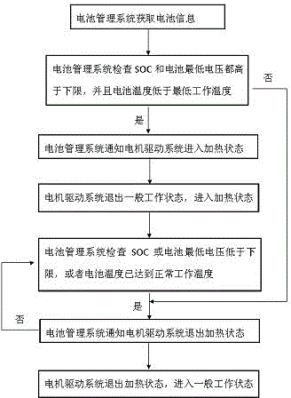
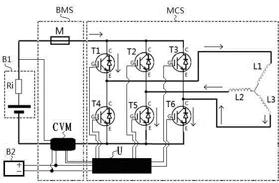
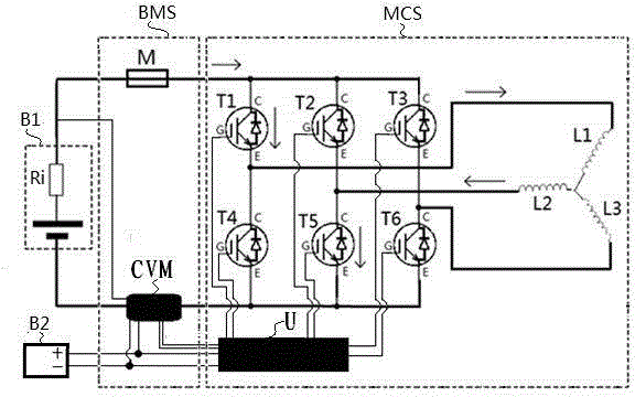
[0027] The battery heating method built into the motor drive system MCS in the first embodiment of the present invention is as follows: figure 1 , figure 2 , image 3 , Figure 4 As shown, it includes: battery management system BMS, motor drive system MCS; the battery management system BMS detects the voltage, current, and temperature of the power battery pack B1 in real time, calculates the remaining power SOC, and performs energy management and heat management on the power battery pack B1. Perform short-circuit protection to prevent the power battery pack B1 from igniting or exploding due to excessive current; the motor drive system MCS includes the control unit U, six IGBT transistors (N-channel insulated gate bipolar transistors) and three stator inductances of the motor, six One IGBT transistor is connected with the three stator inductances of the motor to form a three-phase bridge structure; the battery management system BMS communicates with the motor drive system MC...

no. 2 example

[0039] The second embodiment of the present invention: when the power battery pack B1 is in the heating state, the second IGBT transistor T2 and the sixth IGBT transistor T6 are IGBT transistors used for triggering, and the third IGBT transistor T3 and the fifth IGBT transistor T5 are used for discharging put the IGBT transistor, the second stator inductance L2 and the third stator inductance L3 are energy storage inductances. When the battery pack is in the discharge process, the second IGBT transistor T2 and the sixth IGBT transistor T6 are turned on at the same time, and the current flows from the positive pole of the power battery pack B1 through the fuse M, the second IGBT transistor T2, the second stator inductance L2, and the third stator inductance L3, the sixth IGBT transistor T6, and the current and voltage detection unit CVM return to the negative pole of the power battery pack B1, the current rises, and the energy is stored in the second stator inductance L2 and the...

no. 3 example

[0040] The third embodiment of the present invention: when the power battery pack B1 is in the heating state, the third IGBT transistor T3 and the fourth IGBT transistor T4 are IGBT transistors used for triggering, and the first IGBT transistor T1 and the sixth IGBT transistor T6 are used for discharging put the IGBT transistor, the third stator inductance L3 and the first stator inductance L1 are energy storage inductances. When the battery pack is in the discharge process, the third IGBT transistor T3 and the fourth IGBT transistor T4 are turned on at the same time, and the current flows from the positive pole of the power battery pack B1 through the fuse M, the third IGBT transistor T3, the third stator inductor L3, and the first stator The inductor L1, the fourth IGBT transistor T4, and the current and voltage detection unit CVM return to the negative pole of the power battery pack B1, the current rises, and the energy is stored in the third stator inductor L3 and the first...


PUM


Abstract

The invention discloses a battery heating structure built into a motor driven system, and a method thereof. The method includes the following steps: a battery management system detects and acquires the voltage and the temperature of a power battery pack, and calculates remaining power information; the battery management system notifies the motor driven system to enter a heating state if the detected remaining power of the power battery pack is higher than a lower normal work limit, the lowest voltage is higher than a lower limit and the temperature is lower than a lower normal work temperature limit; the battery management system notifies the motor driven system to quit the heating state if not; the motor driven system quits a general work state and enters the heating state; the battery management system checks the state of the power battery pack in the heating state, and notifies the motor driven system to quit the heating state when the remaining power of the power battery pack or the lowest voltage is lower than the lower limit or the temperature of the power battery pack reaches the normal work temperature; and the motor driven system quits the heating state and enters the general work state. The battery heating built into the motor driven system, and the method thereof realize uniform heating and fast heating speed.

Description

technical field [0001] The invention belongs to the technical field of automotive electronics, and relates to a battery heating method and structure built in a motor drive system; it is especially suitable for heating battery packs of pure electric passenger vehicles. Background technique [0002] With the development of new energy vehicles, lithium battery power battery packs are used more and more widely, and the battery pack will inevitably encounter low temperature environments during use. At low temperatures, the charging and discharging performance of lithium batteries is seriously affected. In this case, the battery cannot be charged, and the discharge efficiency is also greatly reduced. It is necessary to raise the battery temperature to the normal operating temperature by heating. [0003] Most of the existing lithium battery heating systems install a heating film or heater on the lithium battery, start the heating device at low temperature, first heat the outside o...

Claims


Application Information

Patent Timeline
Patent Type & Authority Applications(China)
IPC IPC(8): H01M10/615H01M10/617H01M10/625H01M10/637H02J7/00
CPCH01M10/0525H01M10/443H01M10/48H01M10/486H01M2220/20H02J7/00Y02E60/10
Inventor 王微孙永乐刘志钢董亦鹏陈洪斌
Owner FAWER AUTOMOTIVE PARTS
Why Eureka
Try Eureka