Pyrolysis system and pyrolysis method for organic wastes

A technology of pyrolysis of organic waste, applied in the field of pyrolysis, can solve problems that are rarely mentioned, and achieve the effects of improving heating uniformity, increasing contact area, improving pyrolysis efficiency and pyrolysis degree

Inactive Publication Date: 2015-04-29
BEIJING SHENYUAN ENVIRONMENTAL PROTECTION CO LTD
View PDF7 Cites 16 Cited by
  • Summary
  • Abstract
  • Description
  • Claims
  • Application Information

AI Technical Summary

Problems solved by technology

In the gas heating pyrolysis technology, high-temperature flue gas is often used as a heating carrier to directly enter the pyrolysis furnace and pass through the mat

Method used


Image

  • Pyrolysis system and pyrolysis method for organic wastes
  • Pyrolysis system and pyrolysis method for organic wastes
  • Pyrolysis system and pyrolysis method for organic wastes

Examples


Embodiment 1

[0085] Autumn domestic garbage in a certain area with a particle size of 5mm-120mm (see Table 1 for the analysis data of garbage raw materials) is continuously fed into the rotating bed at a rate of 1.6t / h, and is directly contacted with non-condensable gas at a temperature of about 800°C for heat exchange and heated at 680°C. Pyrolysis occurs to generate hot solid charcoal, oil vapor and combustible gas. The temperature of the obtained hot solid charcoal is about 620°C and enters the cooling system for cooling to recover heat. The cooled solid charcoal is sent to the storage bin . The mixture of oil gas and non-condensable gas for heating is drawn out of the rotating bed through multiple oil and gas outlets on the top of the rotating bed. The temperature of the high-temperature oil and gas mixed with the non-condensable gas is 660°C, and the oil and gas from each oil and gas outlet are combined into cooling through the oil and gas main pipe. in the purification unit.

[0086...

Embodiment 2

[0091] Autumn domestic garbage in a certain area with a particle size of 5mm-120mm is continuously fed into the rotating bed at a rate of 1.3t / h, directly contacts with non-condensable gas at a temperature of about 800°C for heat exchange, and pyrolyzes at 660°C to generate hot solids containing carbon The temperature of the obtained hot solid charcoal is about 640°C and enters the cooling system for cooling to recover heat, and the cooled solid charcoal is sent to the storage bin. The mixture of oil gas and non-condensable gas for heating is drawn out of the rotating bed through multiple oil and gas outlets on the top of the rotating bed. The temperature of the high-temperature oil and gas mixed with the non-condensable gas is 650°C, and the oil and gas from each oil and gas outlet are combined into cooling through the oil and gas main pipe. and purification system.

[0092] The moisture content of domestic garbage in autumn in Hubei is slightly higher, and the gas volume aft...


PUM


Abstract

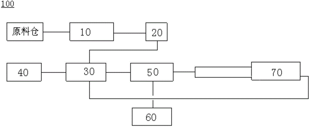
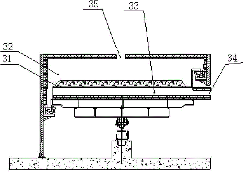
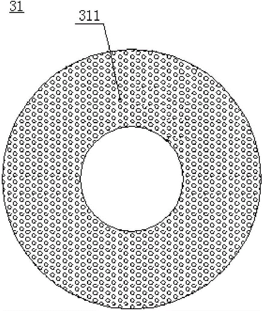
The invention provides a pyrolysis system and pyrolysis method for organic wastes. The pyrolysis system for the organic wastes comprises a crushing device, a drying device, a rotating-bed pyrolysis oven, a pyrolysis solid processing device, a cooling and purifying device, an oil storage tank, and a heat accumulating type rotary heat exchanger, wherein the rotating-bed pyrolysis oven is suitable for performing pyrolysis treatment on pyrolysis raw materials, and a rotatable material distributing tray for containing the pyrolysis raw materials is arranged in the rotating-bed pyrolysis oven, the material distributing tray divides the interior of the rotating-bed pyrolysis oven into a pyrolysis chamber positioned above the material distributing tray and a heat supply chamber positioned below the material distributing tray , wherein a plurality of through holes for enabling the pyrolysis chamber to be communicated with the heat supply chamber are formed in the material distributing tray; the heat accumulating type rotary heat exchanger is connected with the cooling and purifying device and a hot-air inlet of the rotating-bed pyrolysis oven for pyrolyzing heated non-condensable gases. Through the adoption of the pyrolysis system of organic wastes, disclosed by the embodiment of the invention, the organic wastes can be effectively pyrolyzed.

Description

technical field [0001] The invention relates to the field of pyrolysis, in particular, the invention relates to a pyrolysis system and a pyrolysis method for organic waste. Background technique [0002] In view of the large amount of waste in the world, the traditional main methods of waste disposal are landfill, composting and incineration. However, with the rapid increase of waste, these three technologies are increasingly showing their defects. For example, landfill occupies a large area Land, the composting method has a small amount of treatment and low efficiency, and incineration is prone to produce secondary pollution, which will produce harmful gases, especially toxic pollutants such as Dioxins, and is one of the causes of smog weather, making it widely used in industrial Applications are hindered. [0003] Pyrolysis technology is to heat organic matter to 500-1000°C in the absence of oxygen or oxygen, so that solid carbonaceous matter (coal, biomass, garbage, waste...

Claims


Application Information

Patent Timeline
IPC IPC(8): C10B53/00C10B57/10C10B49/04
CPCC10B49/04C10B53/00C10B57/10
Inventor 吴道洪吴小飞肖磊巴玉鑫
Owner BEIJING SHENYUAN ENVIRONMENTAL PROTECTION CO LTD
Why Eureka
Try Eureka